Small capacitance measurement circuit based on AC (alternating current) voltage drop balance and measurement method

A technology for measuring circuits and tiny capacitors. It is used in the measurement of electrical variables, resistance/reactance/impedance, and measurement devices. It can solve problems such as high cost, high signal-to-noise ratio, and complicated circuits, so as to eliminate the influence of stray capacitance. , Improve the common mode rejection ratio, the effect of suppressing temperature drift

Active Publication Date: 2012-05-02
溧阳常大技术转移中心有限公司
View PDF5 Cites 15 Cited by
  • Summary
  • Abstract
  • Description
  • Claims
  • Application Information

AI Technical Summary

Problems solved by technology

[0009] Since the AC phase-locked amplification capacitor measurement circuit uses an AC amplifier, it has low drift and high signal-to-noise ratio, but the circuit is more complicated, the cost is higher, the anti-spur performance still needs to be improved and the resolution can only reach nF level
Chinese patent 201010500688.1 "A microcapacitance measurement method and special device" has improved the AC lock-in amplification method, but the circuit lacks suppression measures for excitation voltage source fluctuations

Method used


Image

  • Small capacitance measurement circuit based on AC (alternating current) voltage drop balance and measurement method
  • Small capacitance measurement circuit based on AC (alternating current) voltage drop balance and measurement method
  • Small capacitance measurement circuit based on AC (alternating current) voltage drop balance and measurement method

Examples


Embodiment Construction

[0034] The present invention is described in further detail now in conjunction with accompanying drawing. These drawings are all simplified schematic diagrams, which only illustrate the basic structure of the present invention in a schematic manner, so they only show the configurations related to the present invention.

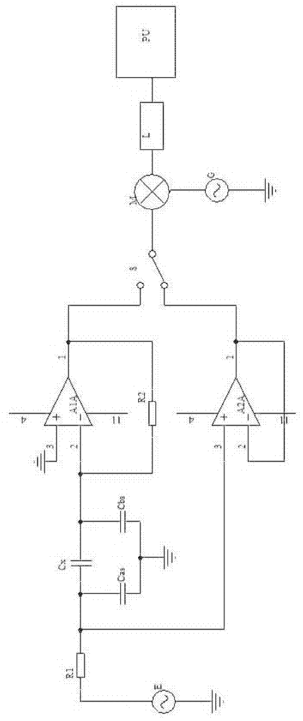
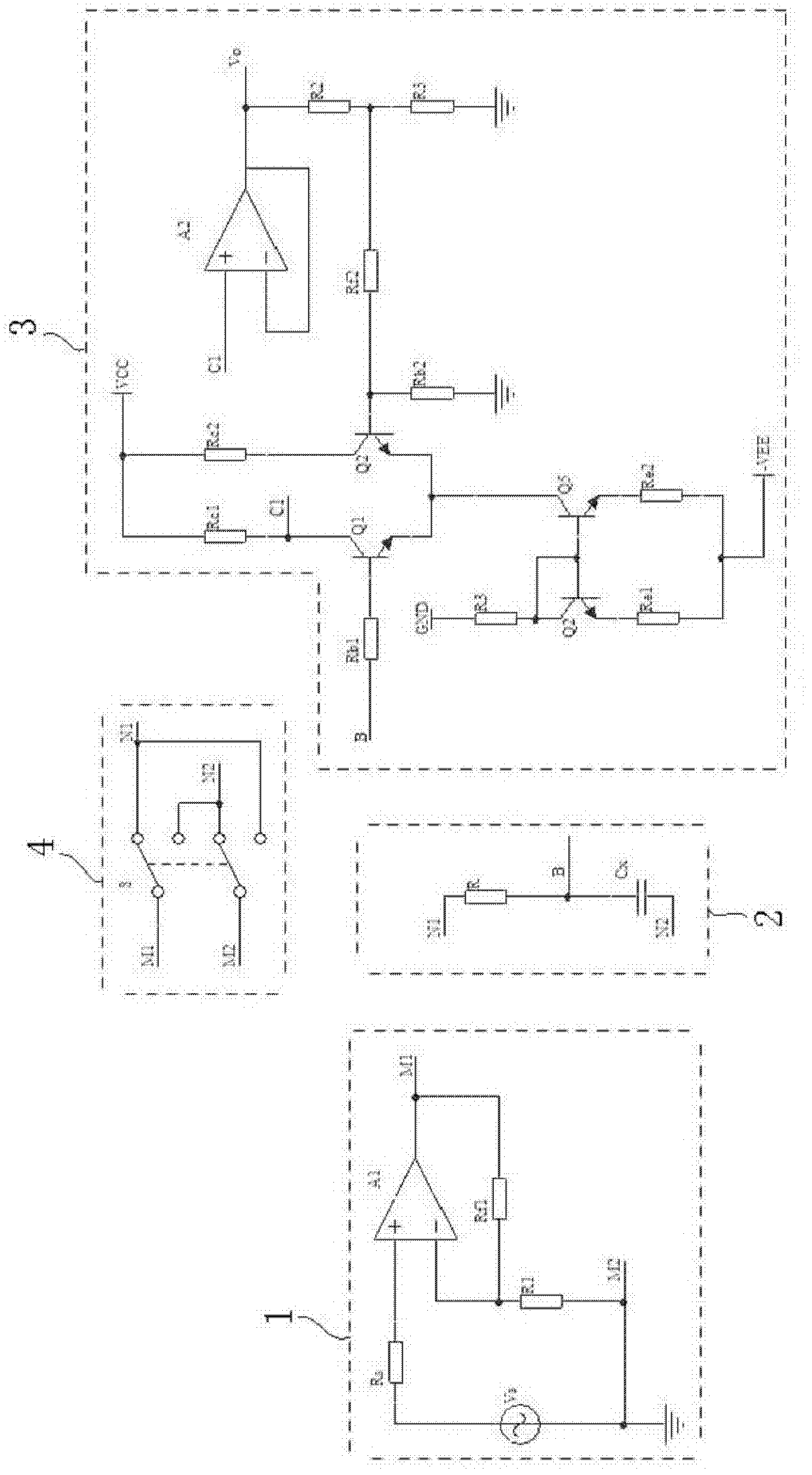
[0035] Such as figure 2 As shown, the microcapacitance measurement principle diagram of the present invention, the input excitation circuit 1 in the figure includes an AC voltage excitation source Vs, a resistor Rs, an operational amplifier A1, a resistor R1 and a feedback resistor Rf1. The output level of the AC voltage source Vs is connected to the positive input terminal of the operational amplifier A1 through the resistor Rs, and the operational amplifier A1 amplifies the input level; the negative feedback network composed of the resistor R1 and the feedback resistor Rf1 converts the output voltage of the operational amplifier A1 to Part of it is fed bac...


PUM


Abstract

The invention relates to a small capacitance measurement circuit based on AC (alternating current) voltage drop balance. The small capacitance measurement circuit comprises an input end excitation circuit, a measurement circuit, an output end detection circuit, and a selector switch circuit for switching input voltage direction of the input end excitation circuit to the measurement circuit; the input end excitation circuit is connected with the measurement circuit through the selector switch circuit; and the input end of the output end detection circuit is connected with a reference resistor of the measurement circuit and a to-be-measured capacitor. The invention also relates to a small capacitance measurement method based on AC voltage drop balance. The measurement method comprises the following steps: a. setting the measurement circuit provided by the invention; b. adjusting state of the selector switch circuit, and recording the frequency of an AC voltage excitation source when thevoltage amplitudes of output ends of the output end detection circuit are equal to each other; and c. deriving and calculating the capacitance of the measured capacitor. The small capacitance measurement circuit can effectively suppress the influences of AC voltage source fluctuation and external noise, well eliminate the influence of stray capacitance, effectively inhibit temperature drift, and improve the zero drift suppression capability.

Description

technical field [0001] The invention relates to the technical field of electronic measurement, in particular to a tiny capacitance measurement circuit and a measurement method based on AC voltage drop balance. Background technique [0002] Capacitance is one of the important physical parameters in electricity. Capacitors are widely used in the design of electronic circuits and the development of electronic products, and the size of the capacitance will directly affect the characteristics of the circuit. In some occasions, it is required to measure the capacitance of a capacitor, such as the capacitance of an unknown parameter, and the capacitance in a capacitive sensor. Therefore, the measurement of capacitance becomes a necessary means. [0003] At present, the micro capacitance measurement methods include resonance method, oscillation method, charging and discharging method, AC bridge method, AC phase-locked amplification capacitance measurement method, capacitance measure...

Claims


Application Information

Patent Timeline
Patent Type & Authority Applications(China)
IPC IPC(8): G01R27/26
Inventor 陈树越王怒
Owner 溧阳常大技术转移中心有限公司
Why Eureka
Try Eureka