
Annular resonant cavity temperature drift compensation method and system thereof

A ring resonant cavity, temperature drift technology, applied in the field of integrated optoelectronics, can solve the problems of red shift of the resonant wavelength of the resonant cavity, unable to work normally, etc., to ensure the effect of process compatibility

Active Publication Date: 2012-05-02
PEKING UNIV
View PDF4 Cites 8 Cited by
  • Summary
  • Abstract
  • Description
  • Claims
  • Application Information

AI Technical Summary

Problems solved by technology

[0012] The technical problem to be solved by the present invention is: how to solve the problem that the resonant wavelength of the ring resonator is red-shifted and cannot work normally when the temperature changes

Method used


Image

  • Annular resonant cavity temperature drift compensation method and system thereof
  • Annular resonant cavity temperature drift compensation method and system thereof
  • Annular resonant cavity temperature drift compensation method and system thereof

Examples


Embodiment 1

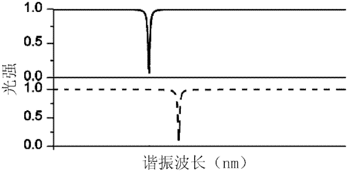
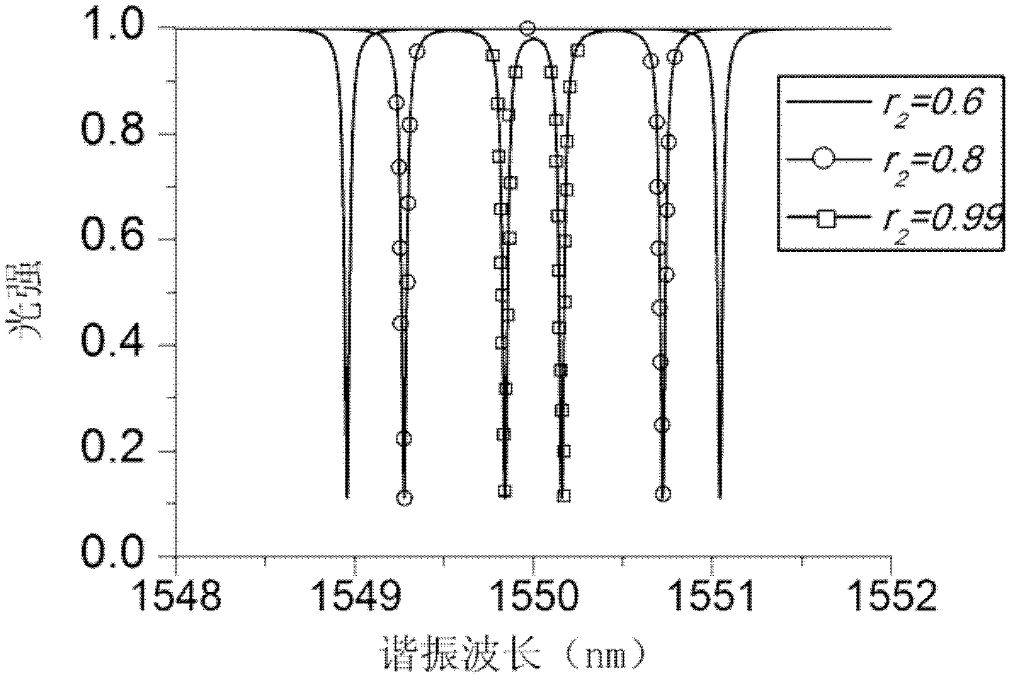
[0077] Such as Figure 5 The structure of the resonant cavity is composed of mutually coupled straight waveguides and a single ring waveguide, and the method of this embodiment includes the following steps:

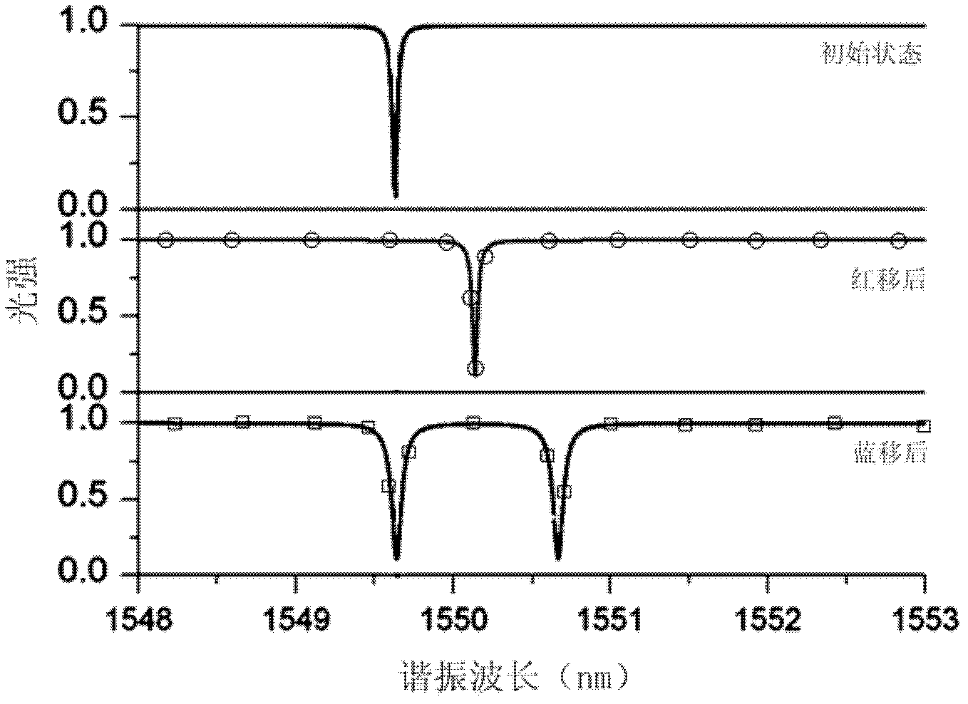
[0078] S101: Obtain the temperature raised by the resonant cavity, and calculate the change amount of the redshift of the resonant wavelength of the resonant ring due to the temperature increase; taking a single-mode silicon waveguide with a width of 500nm as an example, the effective refractive index changes with temperature for When the temperature rises by 5°C, the effective refractive index of the waveguide changes by Δn eff =1.04×10⁻³, determined by formula (1)(2) "red shift" Δλ=0.653nm;

[0079] S102: Determine the equivalent structure of the resonant cavity coupling region according to the structure of the resonant cavity, and determine the effective resonance on the resonant ring that can cause the resonant wavelength to blue shift according to the equivalent s...

Embodiment 2

[0094] Such as Figure 8 As shown, the structure of the resonant cavity is composed of sequentially coupled straight waveguides, a first ring waveguide and a second ring waveguide, and the method of this embodiment includes the following steps:

[0095] S201: Obtain the temperature raised by the resonant cavity, and calculate the change amount of the redshift of the resonant wavelength of the resonant ring due to the temperature rise; taking a single-mode silicon waveguide with a width of 500 nm as an example, the effective refractive index changes with temperature for When the temperature rises by 5°C, the effective refractive index of the waveguide changes by Δn eff =1.04×10⁻³, determined by formula (1)(2) "red shift" Δλ=0.653nm;

[0096] S202: Determine the equivalent structure of the resonant cavity coupling region according to the structure of the resonant cavity, and determine an effective resonance on the resonant ring that can blue-shift the resonant wavelength acco...


PUM


Abstract

The invention discloses an annular resonant cavity temperature drift compensation method and a system thereof and relates to the integrated photoelectron technology field. The method comprises the following steps: S1. acquiring an increased temperature of the resonant cavity and calculating a variation of resonance wavelength redshift of a resonance ring; S2. determining an effective resonance coupling coefficient which can make blue shift of the resonance wavelength on the resonance ring; S3. establishing a corresponding relation between the effective resonance coupling coefficient of the resonant cavity and the variation of the blue shift of the resonance wavelength of the resonant cavity; S4. selecting a compensation resonance coupling coefficient corresponding to the variation of the resonance wavelength redshift according to the corresponding relation; S5. adjusting the effective resonance coupling coefficient to the compensation resonance coupling coefficient. In the invention, through adjusting the effective resonance coupling coefficient of the resonance ring, the resonance wavelength redshift of the resonant cavity caused by temperature change can be avoided and normal working can be performed.

Description

technical field [0001] The invention relates to the technical field of integrated optoelectronics, in particular to a ring resonant cavity temperature drift compensation method and system. Background technique [0002] At present, optical resonant cavities have more and more applications in the fields of communication and sensing. The transmission characteristics of the resonant cavity have the characteristics of wavelength selection, and the specific realizations include Fabry-Perot resonant cavity, ring resonant cavity and so on. Among them, the wavelength selection characteristic of the ring resonator is relatively sensitive, and can distinguish wavelength differences with a difference of 0.01nm. But in general, as the temperature increases, the refractive index of the material will increase, and the resonance wavelength of the resonant cavity will shift to the long wavelength direction, which is called the "red shift" of the resonance spectrum. Therefore, the temperatu...

Claims


Application Information

Patent Timeline
Patent Type & Authority Applications(China)
IPC IPC(8): G02B6/26G02B6/24
Inventor 易华祥周治平
Owner PEKING UNIV
Learn More