
Rotor for permanent magnet motor

A technology for permanent magnet motors and rotors, applied in the direction of magnetic circuit rotating parts, magnetic circuit shape/style/structure, etc., can solve the problems of excessive consumption of magnetic materials, waste of magnetic material resources, and low utilization rate of permanent magnet materials. Achieve the effect of simple structure, uniform magnetic flux and high utilization rate

Inactive Publication Date: 2012-05-02
铜陵浩岩节能科技有限公司
View PDF2 Cites 1 Cited by
  • Summary
  • Abstract
  • Description
  • Claims
  • Application Information

AI Technical Summary

Problems solved by technology

[0002] The motor rotor is an essential part of the motor. At present, the internal structure of the permanent magnet motor produced, sold and used in the market is complicated, and the magnetic material of the motor rotor supporting the motor is too expensive due to blind design, and a large amount of magnetic material is wasted. Resources, conventional permanent magnet synchronous motors, can be used for both constant speed synchronous operation and variable frequency stepless speed regulation synchronous operation; it has the advantages of high efficiency, energy saving, stable operation, and simple control, but the utilization rate of its permanent magnet materials is low , the cost is high, and its popularization and application are limited

Method used


Image

  • Rotor for permanent magnet motor
  • Rotor for permanent magnet motor
  • Rotor for permanent magnet motor

Examples


Embodiment Construction

[0019] In order to make the purpose, technical solution and advantages of the present invention clearer, the present invention will be further described in detail below in conjunction with the accompanying drawings and an embodiment with four magnetic poles. It should be understood that the specific embodiments described here are only used to explain the present invention, not to limit the present invention.

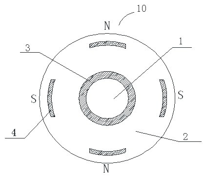
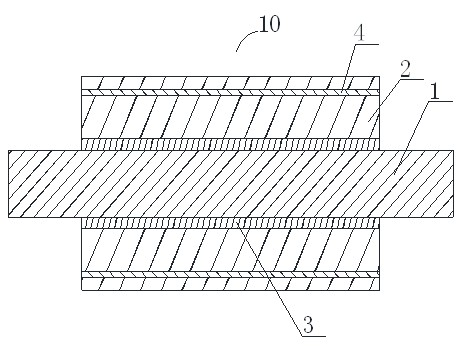
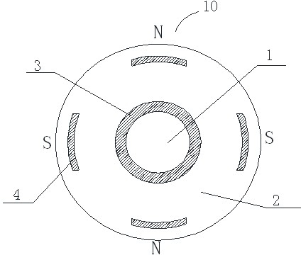
[0020] see figure 1 and figure 2 , figure 1 It is a side sectional view of the rotor 10 of the permanent magnet motor of the present invention, figure 2 It is a front sectional view of the rotor 10 of the permanent magnet motor of the present invention.

[0021] A rotor 10 of a permanent magnet motor, comprising a rotating shaft 1, an iron core 2, a magnetic isolation sleeve 3, and a permanent magnet 4, the rotor 10 is a whole, the rotating shaft 1 is wrapped in the magnetic isolation sleeve 3, and the magnetic isolation sleeve 3 The magnetic sleeve 3 is wrapped in...


PUM


Abstract

The invention provides a rotor for a permanent magnet motor. The rotor for the permanent magnet motor comprises a rotating shaft, a core, a magnetic shield and a permanent magnet, wherein the rotor is integral; the rotating shaft is covered by the magnetic shield; the magnetic shield is covered by the core; the rotating shaft, the magnetic shield and the core share the same axial center; and the permanent magnet is covered by the core. The permanent magnet motor not only has the advantages of the normal motor but also is simple in structure, and has higher use ratio of a magnetic material. The core is easy to magnetize after being processed by low-carbon steel so that a magnetic flow in each grade is uniform. By designing the rotor in an integral structure and sealing the permanent magnet inside the rotor, the occurrence of breaking the permanent magnet is reduced even if no permanent magnets are broken. The rotating shaft is coated by a magnetic insulation material so that no magnetism leakage is mainly generated. In the same condition, 30-40% of magnetic steel can be saved, thereby greatly saving the cost.

Description

technical field [0001] The invention relates to the field of motors, in particular to a rotor of a permanent magnet motor. Background technique [0002] The motor rotor is an essential part of the motor. At present, the internal structure of the permanent magnet motor produced, sold and used in the market is complicated, and the magnetic material of the motor rotor supporting the motor is too expensive due to blind design, and a large amount of magnetic material is wasted. Resources, conventional permanent magnet synchronous motors, can be used for both constant speed synchronous operation and variable frequency stepless speed regulation synchronous operation; it has the advantages of high efficiency, energy saving, stable operation, and simple control, but the utilization rate of its permanent magnet materials is low , the cost is higher, and its popularization and application are limited. Contents of the invention [0003] In view of this, it is necessary to provid...

Claims


Application Information

Patent Timeline
Patent Type & Authority Applications(China)
IPC IPC(8): H02K1/27H02K1/28
Inventor 杨镇
Owner 铜陵浩岩节能科技有限公司
Learn More