

Wedge-shaped pre-tightened sandwich type rectangular four-pin linear ultrasonic motor vibrator
A linear ultrasonic motor, sandwich-type technology, applied in the direction of piezoelectric effect/electrostrictive or magnetostrictive motors, generators/motors, electrical components, etc., can solve the problems of complex structure, high processing and assembly precision requirements, etc. , to achieve the effects of improving mechanical output capability, simplifying the structure of the vibrator, and flexibly designing
- Summary
- Abstract
- Description
- Claims
- Application Information
AI Technical Summary
Problems solved by technology
Method used
Image

Examples
specific Embodiment approach 1
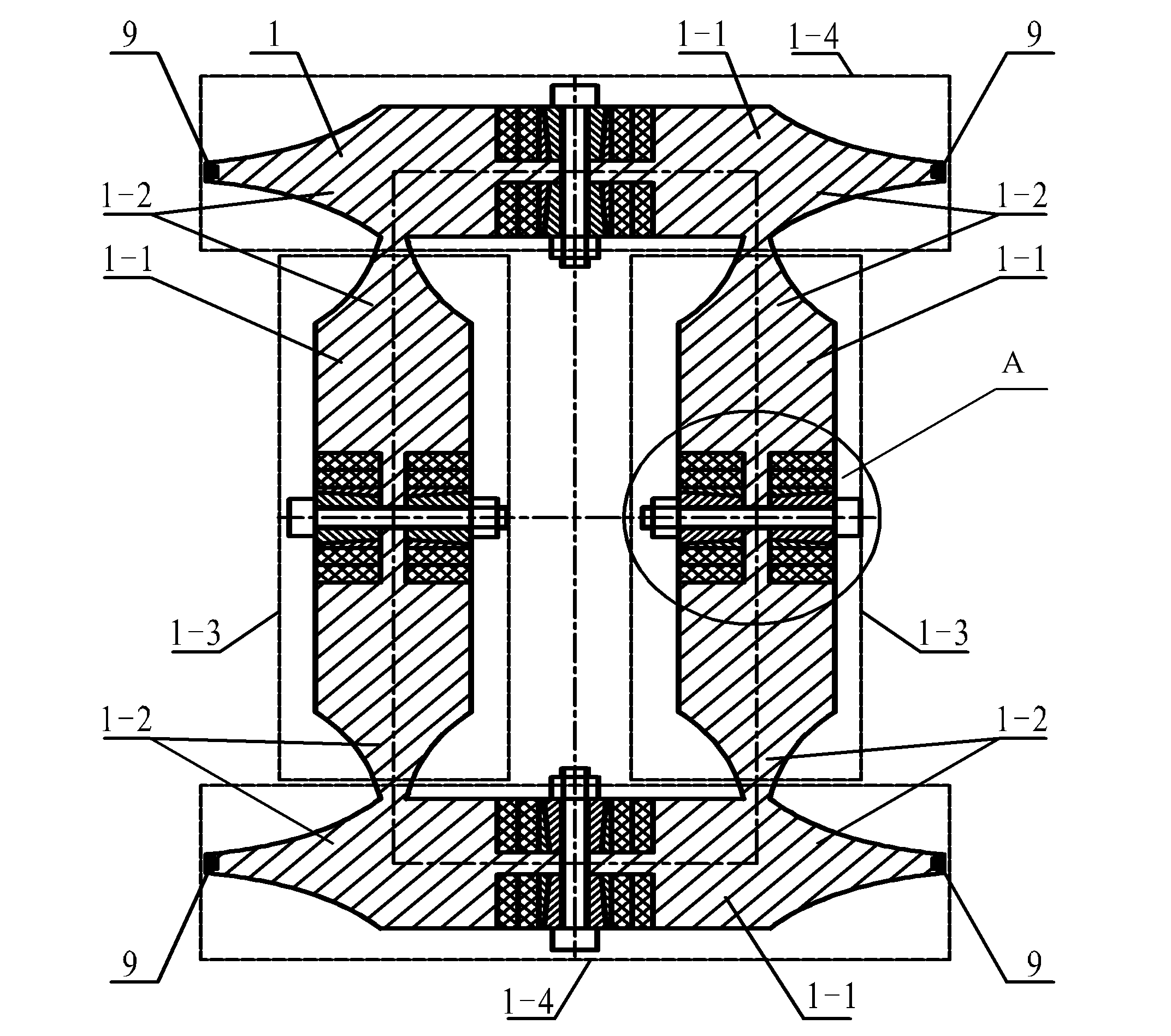
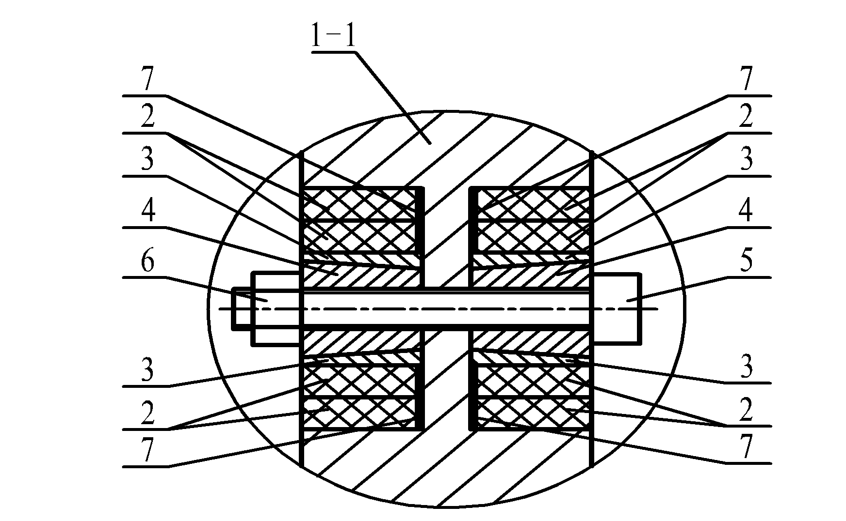
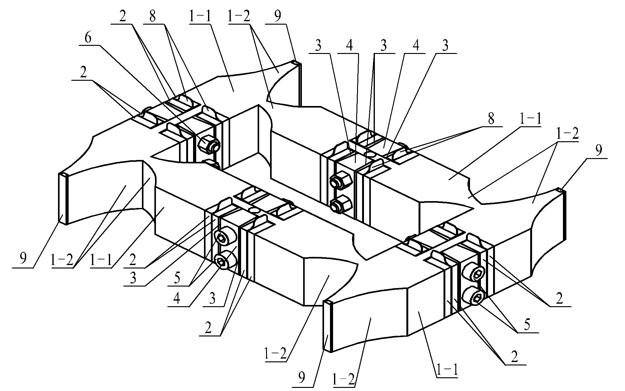
[0026] Specific implementation mode one: the following combination Figure 1 to Figure 4 Describe this embodiment, the sandwich-type quadruped linear ultrasonic motor vibrator adopting wedge-shaped pretension described in this embodiment, which includes a rectangular metal base 1, sixteen pairs of longitudinal vibration piezoelectric ceramic sheets 2, sixteen wedge-shaped blocks 3, Eight preloading blocks 4, preloading screws 5, preloading nuts 6, sixteen insulating gaskets 7 and sixteen electrode sheets 8,
[0027] The rectangular metal matrix 1 is composed of four composite beams of the same shape, divided into two horizontal composite beams 1-4 and two vertical composite beams 1-3,
[0028] Each composite beam is composed of a column beam 1-1 and two horns 1-2, the beam 1-1 is a quadrangular prism with a rectangular cross section, and the horn 1-2 is a rectangular cross section And gradually thinner quadrangular prism, two horns 1-2 are respectively arranged at the two end...
specific Embodiment approach 2
[0036] Specific implementation mode two: the following combination figure 1 , image 3 with Figure 4 Describe this embodiment, this embodiment is a further description of Embodiment 1, this embodiment also includes four friction plates 9,
[0037] The small end surface of the horn 1-2 of each horizontal composite beam 1-4 is provided with a long strip-shaped slot along its thickness direction, and the friction plate 9 is fixed on the horn 1-2 through the strip-shaped slot. 2 on the small end face.
specific Embodiment approach 3
[0038] Specific implementation mode three: the following combination image 3 with Figure 4 This embodiment is described. This embodiment is a further description of Embodiment 2. The friction plate 9 in this embodiment is covered on the small end surface of the horn 1-2 of the horizontal composite beam 1-4, and the friction plate The shape of the outer end face of 9 is identical with the shape of the place small end face.
PUM
 Abstract
Description
Claims
Application Information