Partition excitation type composite bending vibration linear ultrasonic motor oscillator

A linear ultrasonic motor, bending vibration technology, applied in the direction of generator/motor, piezoelectric effect/electrostrictive or magnetostrictive motor, electrical components, etc. Reasonable, inconsistent vibration characteristics of the driving foot, etc., to achieve the effect of improving electromechanical coupling efficiency, improving mechanical output capability, and stable performance

Inactive Publication Date: 2012-05-02
HARBIN INST OF TECH
View PDF3 Cites 7 Cited by
  • Summary
  • Abstract
  • Description
  • Claims
  • Application Information

AI Technical Summary

Problems solved by technology

[0004] In order to solve the problem of inconsistent vibration characteristics of the driving feet of the existing bending vibration mode beam type linear ultrasonic motor vibrato

Method used


Image

  • Partition excitation type composite bending vibration linear ultrasonic motor oscillator
  • Partition excitation type composite bending vibration linear ultrasonic motor oscillator
  • Partition excitation type composite bending vibration linear ultrasonic motor oscillator

Examples


specific Embodiment approach 1

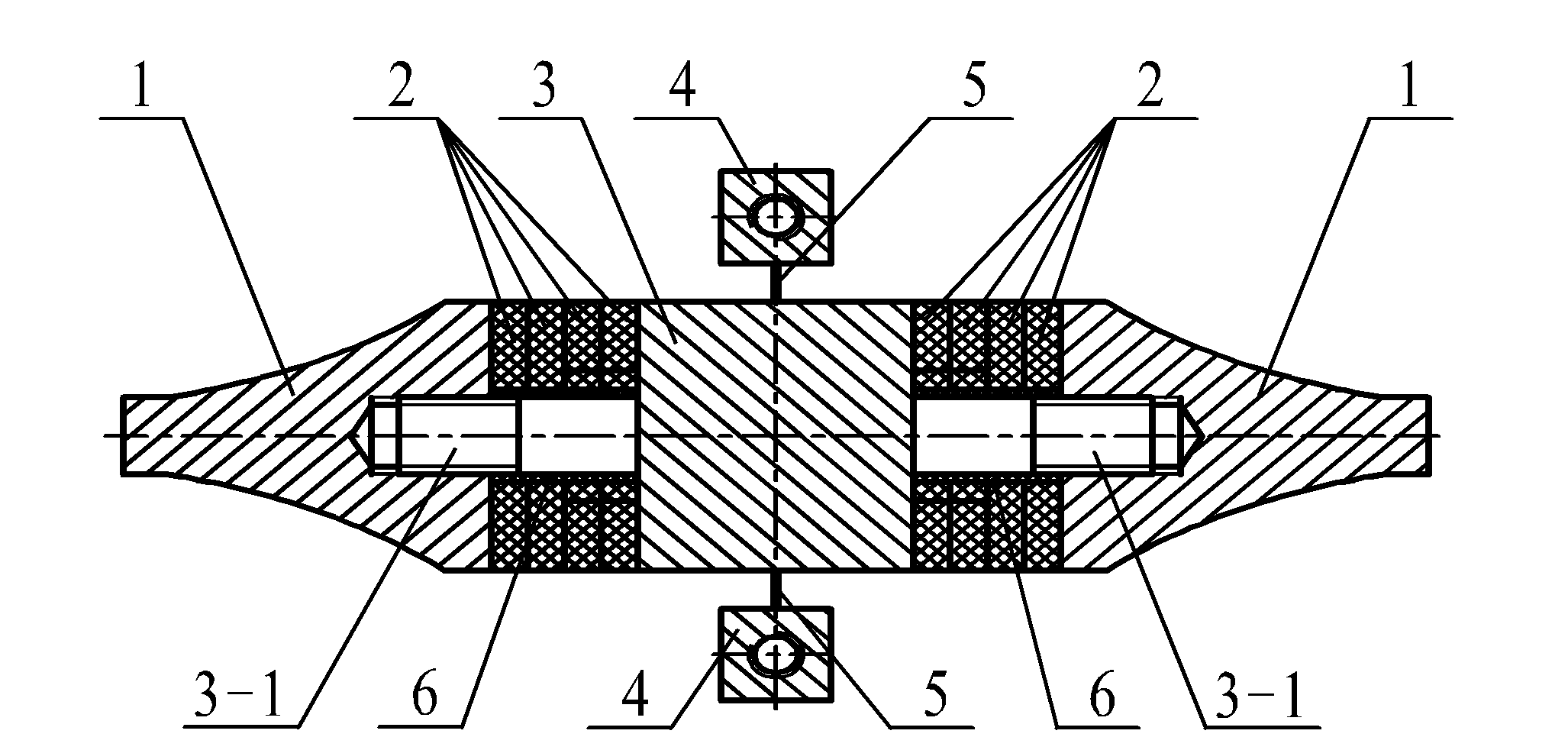
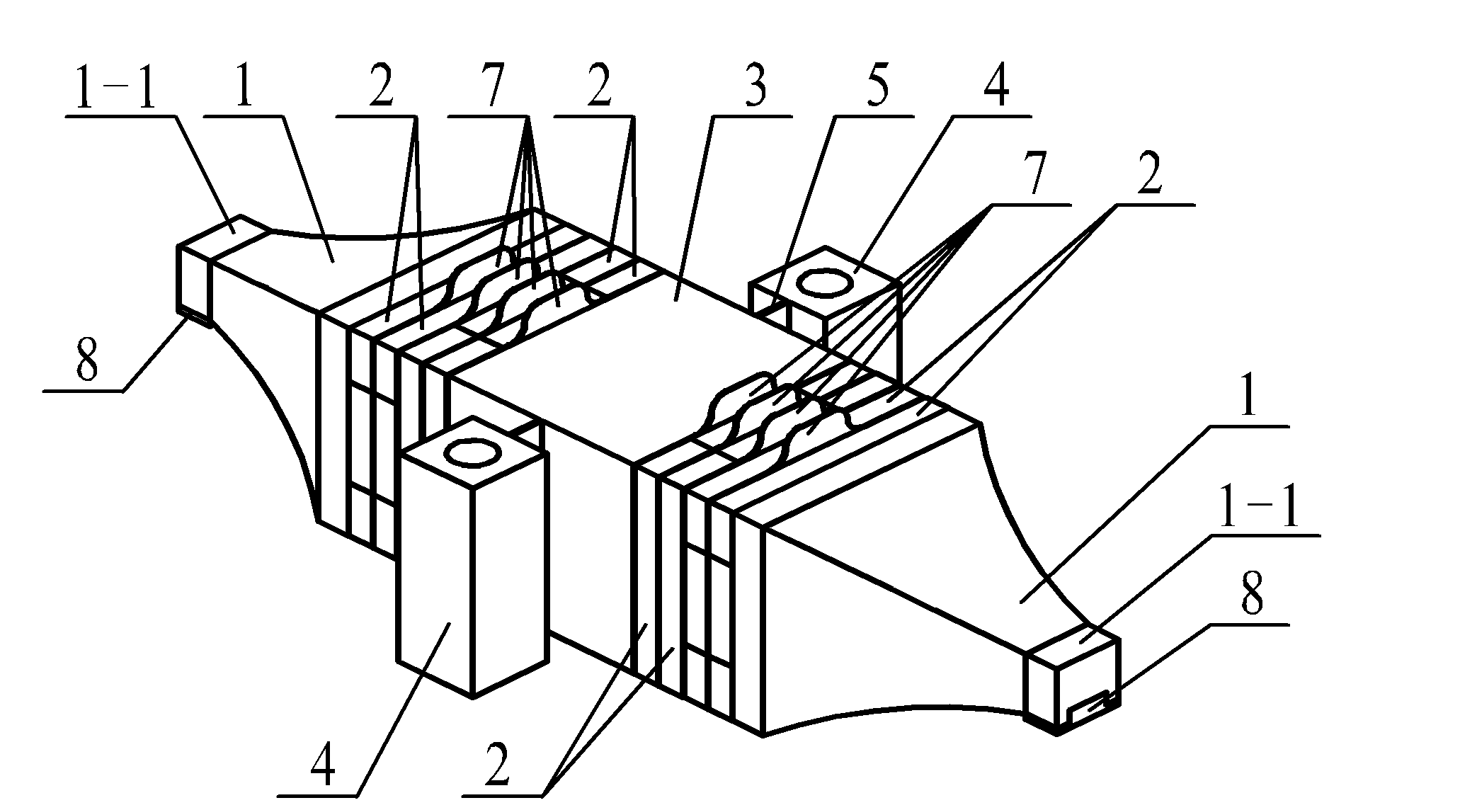
[0028] Specific implementation mode one: the following combination figure 1 and figure 2 Describe this embodiment, the section-excited compound bending vibration linear ultrasonic motor vibrator in this embodiment, which includes two driving feet 1-1, two end covers 1, four pairs of bending vibration piezoelectric ceramic sheets 2, and flanges 3 , two thin-walled beams 5, two mounts 4, insulating sleeves 6 and eight electrode sheets 7,

[0029] The end cap 1 is a block with a square or circular cross-section and tapering. There is a blind hole with an internal thread in the center of the large end face of the end cap 1.

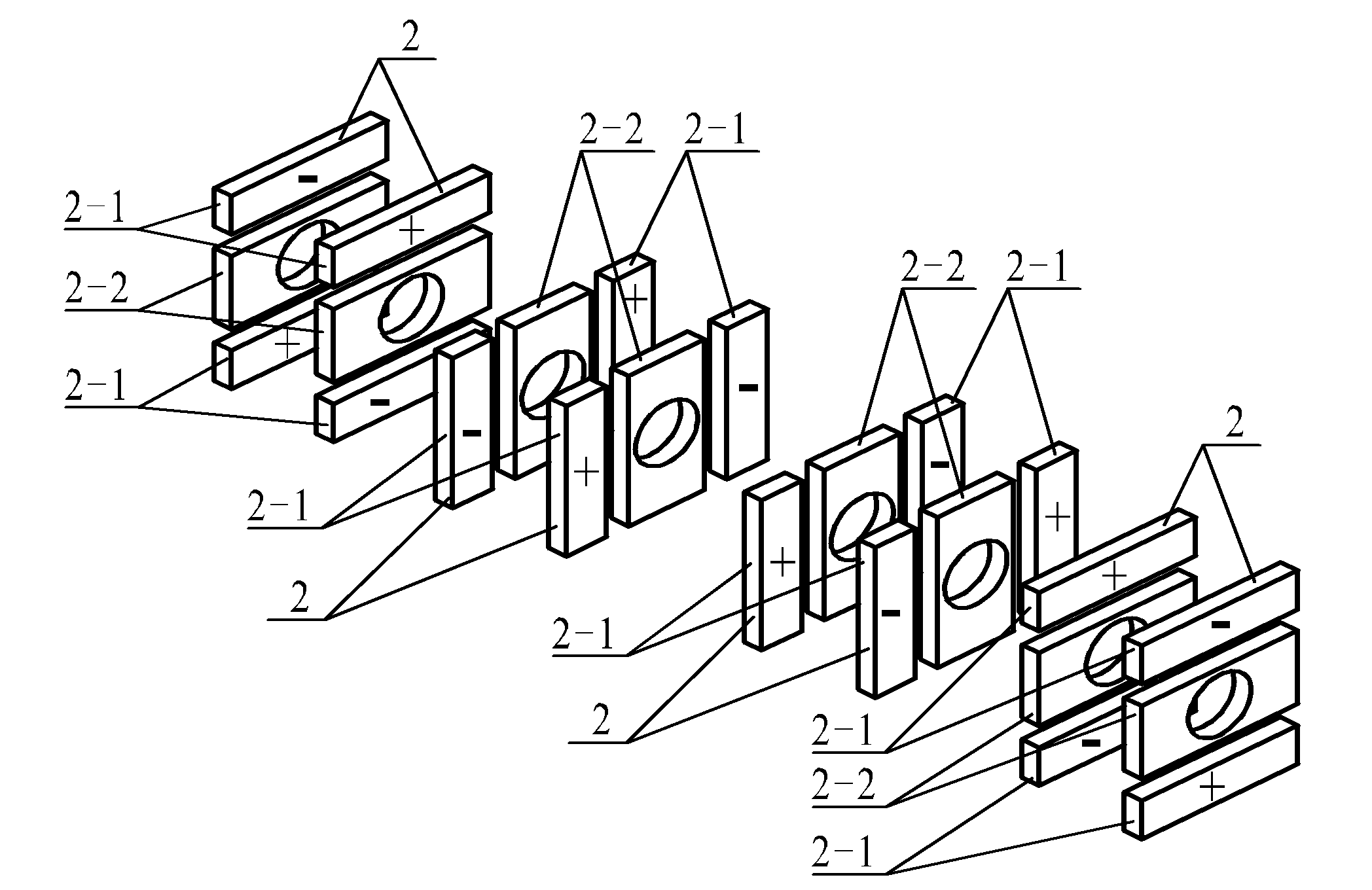
[0030] A stud 3-1 is arranged at the center of the two end faces of the flange 3, and each stud 3-1 is socketed with two pairs of bending vibration piezoelectric ceramic sheets 2, and the end of each stud 3-1 The part is screwed with the blind hole of an end cover 1, and the two pairs of bending vibration piezoelectric ceramic sheets 2 are pressed tightly....

specific Embodiment approach 2

[0039] Specific implementation mode two: the following combination figure 2 Describe this embodiment, this embodiment is a further description of Embodiment 1, this embodiment also includes two friction plates 8,

[0040] The output coupling side of each driving foot 1 - 1 is provided with a rectangular groove, and a friction plate 8 is arranged in the rectangular groove.

specific Embodiment approach 3

[0041] Embodiment 3: This embodiment is a further description of Embodiment 1 or 2. The cross-section of the bending vibration piezoelectric ceramic sheet 2 in this embodiment is square.


PUM


Abstract

The invention provides a partition excitation type composite bending vibration linear ultrasonic motor oscillator, belonging to the piezoelectric ultrasonic motor technology field. Problems that drive foot vibration characteristics of a present bending vibration modal girder type linear ultrasonic motor oscillator are inconsistent, and cutting combination arrangement of bending vibration piezoelectric ceramic sheets is not reasonable are solved. A center of a large end plane of an end cap is provided with a blind hole with internal screw thread. A flange is provided with two studs, each stud is in joint connection with two pairs of bending vibration piezoelectric ceramic sheets, and an end part of a stud is matched with the blind hole through screwing. An electrode slice is provided between adjacent bending vibration piezoelectric ceramic sheets and between a bending vibration piezoelectric ceramic sheet and a contact surface of the flange. The studs are provided with insulation sleeves. Two side surfaces of the flange are provided with two thin walled beams. Outboard of each of the thin walled beams is provided with an installation seat. A small end plane of the end cap is provided with a drive foot. Each bending vibration piezoelectric ceramic sheet is split into two no-bore rectangular piezoelectric ceramic sheets with a same size at two ends and a center hole rectangular piezoelectric ceramic sheet in the middle. The invention is applied to an ultrasonic motor oscillator.

Description

technical field [0001] The invention relates to a section-excited composite bending-vibration linear ultrasonic motor vibrator, which belongs to the technical field of piezoelectric ultrasonic motors. Background technique [0002] Piezoelectric ultrasonic motor is a kind of piezoelectric ultrasonic motor that uses the inverse piezoelectric effect of piezoelectric ceramics to excite vibration in the ultrasonic frequency range in the elastic body, and forms a particle motion with a specific trajectory at a specific point or area on the surface of the elastic body, and then passes through the stator, The frictional coupling between the rotors converts the microscopic motion of the particle into the macroscopic motion of the rotor. It has the advantages of low speed and high torque, no need for a speed change mechanism, no electromagnetic interference, fast response, and self-locking when power is off. [0003] Sandwich Ultrasonic Motor Using Piezoelectric Ceramics with High Ele...

Claims


Application Information

Patent Timeline
IPC IPC(8): H02N2/04
Inventor 刘英想刘军考杨小辉陈维山石胜君
Owner HARBIN INST OF TECH
Why Eureka
Try Eureka