
Wireless network routing method based on directive antenna

A technology of wireless network and directional antenna, applied in the field of wireless network routing and wireless network routing based on directional antenna, it can solve the problem of not providing a solution to the problem of mobility limitation in directional antenna network, ignoring the optimization and effective utilization of wireless network resources, etc.

Active Publication Date: 2012-05-02
SHANGHAI FUDAN COMM
View PDF4 Cites 16 Cited by
  • Summary
  • Abstract
  • Description
  • Claims
  • Application Information

AI Technical Summary

Problems solved by technology

[0006] To sum up, in the communication network routing mechanism based on directional antennas proposed now, either it does not provide a solution to the problem of limited mobility in the directional antenna network, or directly avoids this key problem by adding an omnidirectional communication mode, or ignores Optimization and effective utilization of wireless network resources by multi-service flows in practical applications

Method used


Image

  • Wireless network routing method based on directive antenna
  • Wireless network routing method based on directive antenna
  • Wireless network routing method based on directive antenna

Examples


Embodiment Construction

[0060] In order to make the technical means, creative features and objectives of the present invention easy to understand, the present invention is further described below in conjunction with specific embodiments.

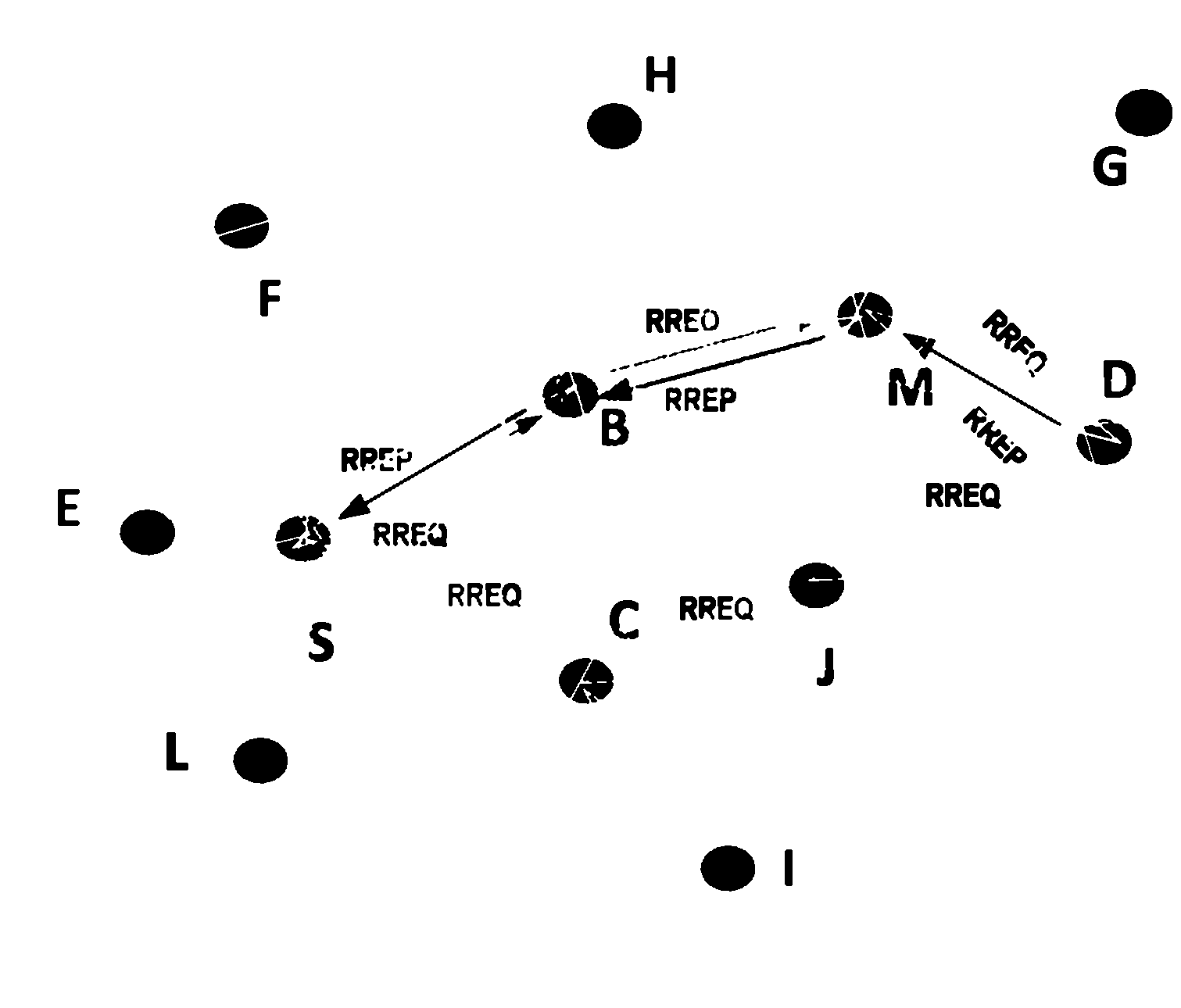
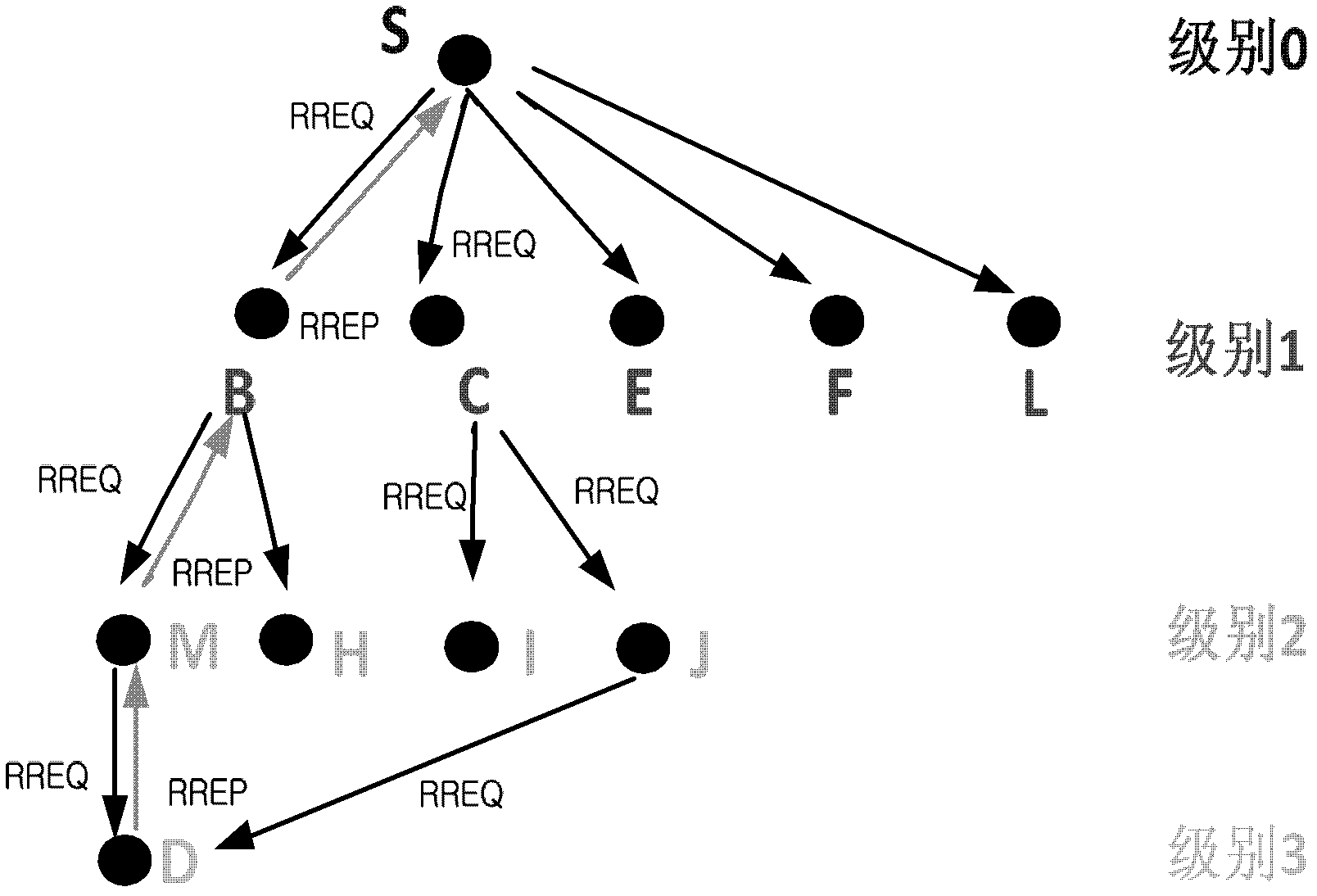
[0061] This embodiment adopts figure 1 The network topology shown, figure 2 It is a link tree structure diagram. figure 1 There are 11 nodes in the network, among which node S is the source node and node D is the destination node. Assume that the parameters of each node are shown in the table below, and here set the bandwidth and the Delay accumulation filter thresholds as: η=2, ξ=10 respectively.

[0062] node

Node Neighbor Node Table

The bandwidth of the corresponding node in the node and its neighbor node table

Node data rate

S (source)

{B,C,E,F,L}

{6,6,3,10,2}

4

B

{S, F, M, H}

{4,9,4,2}

2

C

{S,I,J}

{6,7,8}

3

E

{S}

{3}

2

F

{S, ...


PUM


Abstract

The invention discloses a wireless network routing method based on a directive antenna. The wireless network routing method based on the directive antenna comprises the following steps of: eliminating a path-diffused loop by introducing a node level configuration, and ensuring that a path request message is quickly diffused to a target node; planning an optimal path decision by the target node in a process of reverse feedback replied by the path so as to prevent directional delay caused by path request feedback of each link under the condition that a source node makes a decision; and timely and effectively establishing communication link through a communication azimuth angle with a next jumping node recorded by a middle node when the path requests a replay and backward feedback so as to reduce sweep delay introduced by the directional communication of the node. According to the invention, requirements of an on-demand communication service of the source node on QoS (Quality of Service) of the link are fully considered, and a level concept into the node in a process of establishing a route is introduced; and in addition, by a distributive processing method, a self-adaptive distributive QoS route is finally established by quick conditional forwarding of the middle node and an optimal decision of the target node.

Description

technical field [0001] The invention relates to a wireless network routing method, in particular to a directional antenna-based wireless network routing method, and belongs to the technical field of wireless communication. Background technique [0002] The application of directional antennas in wireless networks will greatly improve the confidentiality of wireless communication, especially in military communication networks, increase communication distance, improve network space utilization, and increase network capacity. , especially one of the hotspots in the field of military communication applications. However, it should be noted that the above-mentioned advantages brought by the introduction of directional antennas are at the cost of reduced overall network mobility, which will greatly reduce the diffusion efficiency of network information, such as routing link information, routing establishment and maintenance information As well as the diffusion of business-oriented ...

Claims


Application Information

Patent Timeline
IPC IPC(8): H04W40/02
Inventor 冯平周海波刘勃归琳李颖熊箭
Owner SHANGHAI FUDAN COMM
Learn More