Feeding device of tin-cutting and sending integrated chip mounter

A chip mounter and tin-feeding technology, applied in the field of tin-cutting and tin-feeding integrated chip mounter feeding equipment, can solve the problems of complicated packaging, restricted production efficiency, and expensive unit price of tin particles, and achieve simple structure and convenient installation and docking Effect

Active Publication Date: 2012-05-02
SHENZHEN JT AUTOMATION EQUIP CO LTD
View PDF3 Cites 3 Cited by
  • Summary
  • Abstract
  • Description
  • Claims
  • Application Information

AI Technical Summary

Problems solved by technology

[0002] In the SMT industry, when many components on the PCB (printed circuit board) are soldered, in order to ensure the quality of the soldering, tin particles need to be added to the soldering place; the tin particles are placed to the required position by a placement machine or other mounting equipment ; However, the current practice in the industry is to buy imported tin pellets. Therefore, the incoming material has been packaged in the form of a tape, which can directly use the ready-made mounter feeder (referred to as "feeder" in the industry) However, it has the following disadvantages: (1) In view of its complicated packaging, the unit price of the originally cheap tin particles becomes very expensive; (2) There is still no integrated tin-cutting and tin-feeding Chip machine feeding equipment, therefore, can not use tin coil raw materials on the market, but also restricts production efficiency to a certain extent; (3) The installation has certain limitations, and can only be connected with the corresponding chip mounter, which cannot meet Other placement / soldering equipment requirements

Method used


Image

  • Feeding device of tin-cutting and sending integrated chip mounter
  • Feeding device of tin-cutting and sending integrated chip mounter
  • Feeding device of tin-cutting and sending integrated chip mounter

Examples


Embodiment Construction

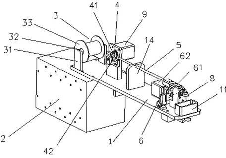
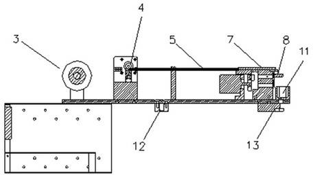
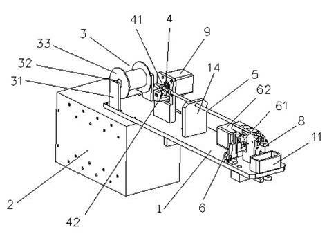
[0021] Such as figure 1 and figure 2 As shown, a feeding device for a tin-cutting and tin-feeding integrated placement machine, which includes a main mounting board 1 and a control electric box 2, is characterized in that, the main mounting board 1 is respectively provided with coils in the order of front and back. Tin device 3, tin wire transmission wheel 4, guide pipe 5, tin cutter 6, tin particle guide groove 7 and tin particle positioning sensor 8, tin wire transmission wheel 4 is connected with transmission wheel motor 9, and guide pipe 5 straddles the tin Between the wire drive wheel 4 and the tin cutter 6, a tin particle guide groove 7 is arranged between the tin cutter 6 and the tin particle positioning sensor 8, and the control electric box 2 is connected with the transmission wheel motor 9, the tin cutter 6 and the tin particle respectively. The positioning sensor 8 is electrically connected, the main mounting plate 1 is provided with a plurality of support plates ...


PUM


Abstract

The invention discloses a feeding device of tin-cutting and sending integrated chip mounter, comprising a main mounting board and a control electrical cabinet, wherein the main mounting board is respectively provided with a tin roller, a tin wire transmission wheel, a guide tube, a tin cutter, a tin particle guiding groove and a tin particle location sensor in sequence, wherein the tin wire transmission wheel is connected with a transmission wheel motor; the guide tube is spanned between the tin wire transmission wheel and the tin cutter; a tin particle guiding groove is installed between the tin cutter and the tin particle location sensor; the control electrical cabinet is respectively connected with the transmission wheel motor, the tin cutter and the tin particle location sensor. The feeding device of tin-cutting and sending integrated chip mounter has the advantages of simple and rational structure, short transmission distance, rapid speed and high efficiency, random adjustment of tin particle size and tin sending speed, and high tin particle location precision, and can take tin roll as the raw material and synchronously finishes the tin sending/cutting process, and obviously reduces the using cost without generating the packing material waste.

Description

technical field [0001] The present invention relates to the field of electronic surface mount (i.e.: SMT mount) / welding technology, more specifically, it relates to a feeding device for a chip mounter integrated with tin cutting and feeding, which is mainly a chip mounter or Other placement / soldering equipment supplies bulk tin pellets. Background technique [0002] In the SMT industry, when many components on the PCB (printed circuit board) are soldered, in order to ensure the quality of the soldering, tin particles need to be added to the soldering place; the tin particles are placed to the required position by a placement machine or other mounting equipment ; However, the current practice in the industry is to buy imported tin pellets. Therefore, the incoming material has been packaged in the form of a tape, which can directly use the ready-made mounter feeder (referred to as "feeder" in the industry) However, it has the following disadvantages: (1) In view of its compli...

Claims


Application Information

Patent Timeline
Patent Type & Authority Applications(China)
IPC IPC(8): H05K3/34
Inventor 洪军向宏文
Owner SHENZHEN JT AUTOMATION EQUIP CO LTD
Why Eureka
Try Eureka