
Apparatus and method for separation of phases in a multiphase flow

A technology of multiphase flow and eddy current, which is applied in the field of equipment and methods for separating phases in multiphase flow, can solve problems such as inability to treat wastewater, and achieve improved separation effects

Inactive Publication Date: 2012-05-02
SORBWATER TECH AS
View PDF8 Cites 17 Cited by
  • Summary
  • Abstract
  • Description
  • Claims
  • Application Information

AI Technical Summary

Problems solved by technology

[0034] A limitation of the known methods is that they are not well suited for the treatment of the large volumes of wastewater produced when oil droplets smaller than 5-10 microns are to be removed

Method used


Image

  • Apparatus and method for separation of phases in a multiphase flow
  • Apparatus and method for separation of phases in a multiphase flow

Examples


Embodiment Construction

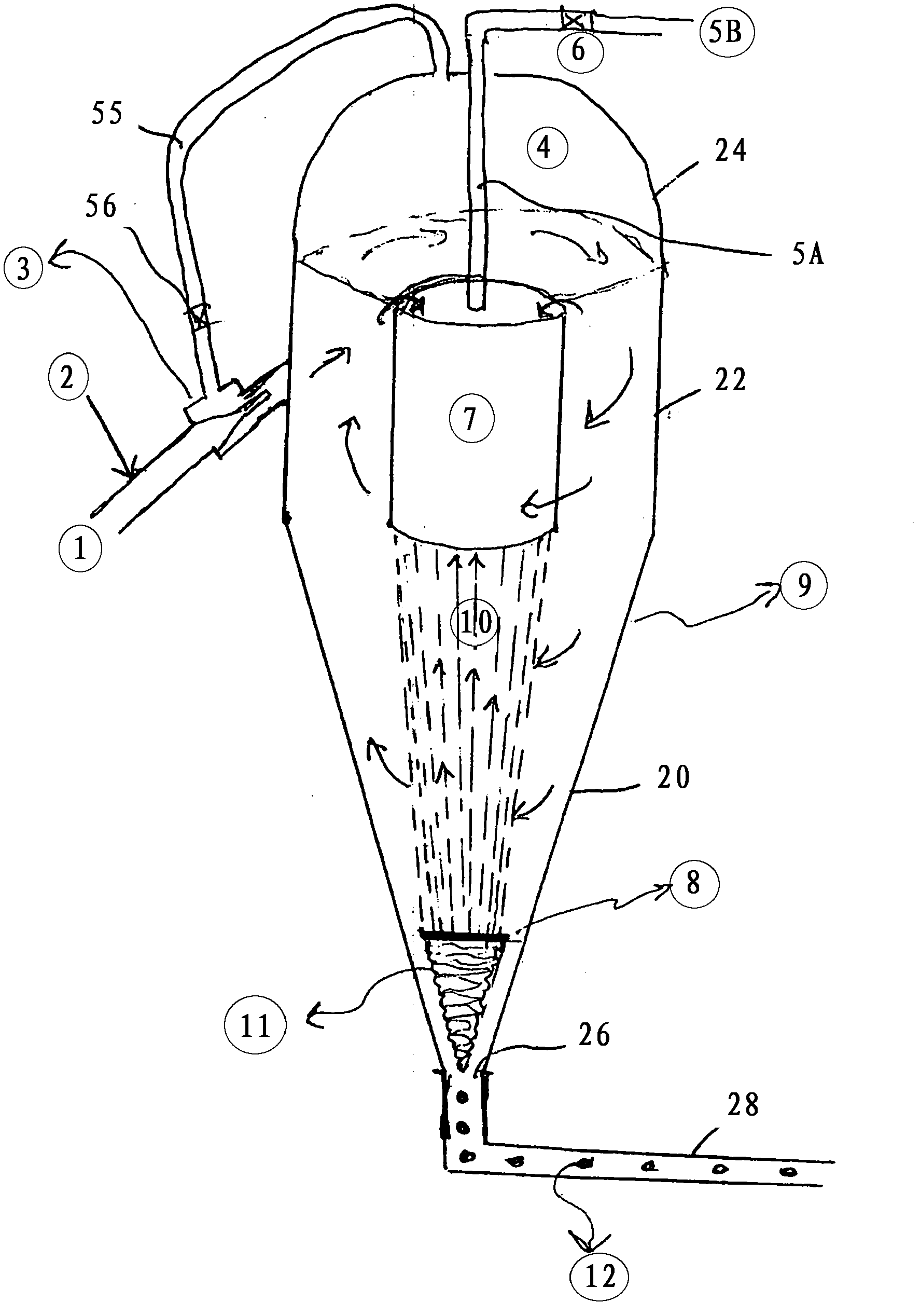
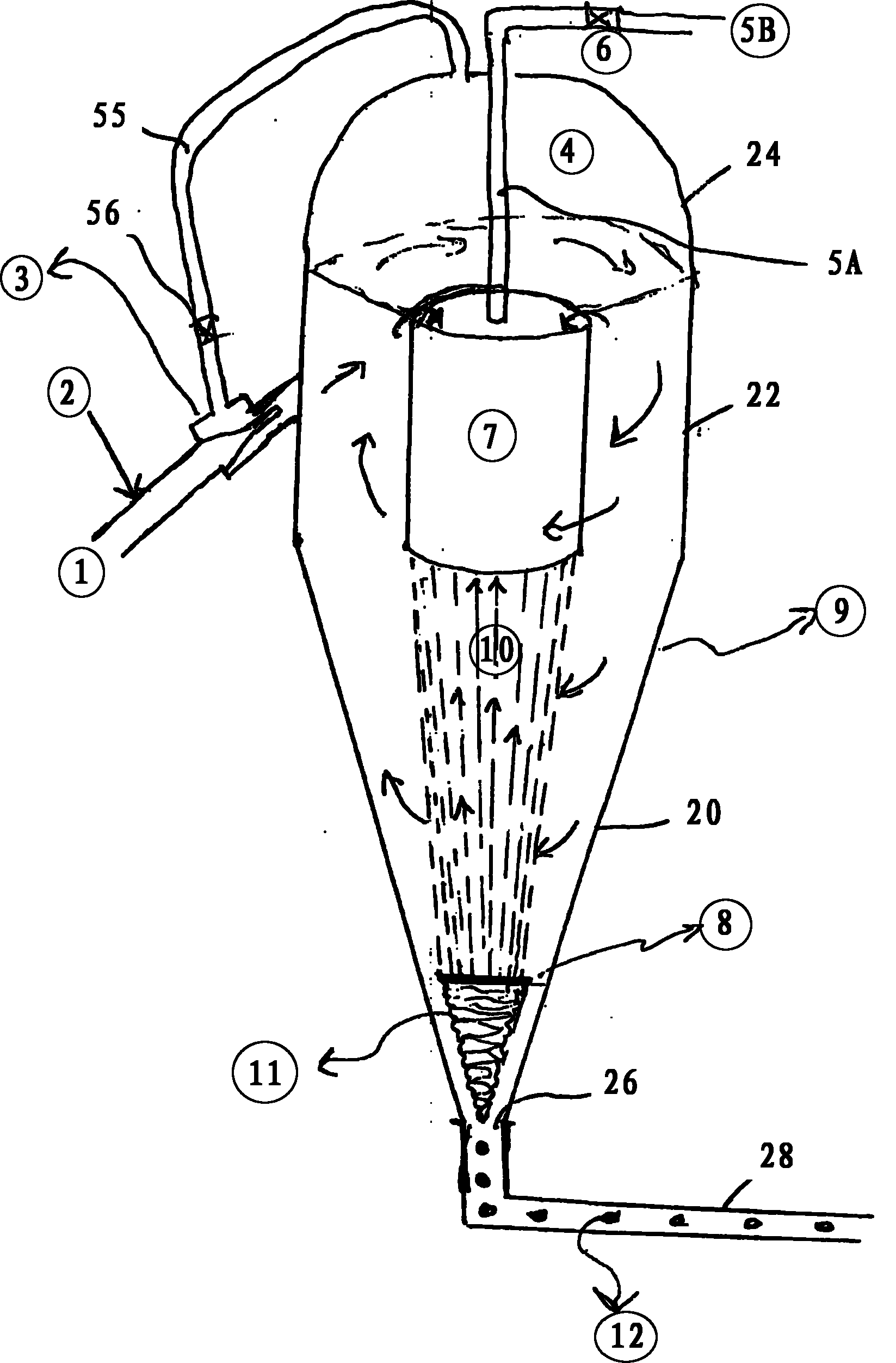
[0078] figure 1 A device according to the invention is shown which is used to carry out the method according to the invention.

[0079] The apparatus comprises a treatment tank 9 (flotation cyclone tank) having a conical bottom portion 20 (like a cornet), an upper cylindrical tank portion 22, and an upper top portion 24 which Can be dome shaped. This is just an example of shapes. In the bottom tip of the conical section 20 there is an outlet 26 to which a draft tube 28 is fitted.

[0080] In the upper part and in the middle of the tank 9 there is arranged a general vortex director 7 which is a cylinder for influencing the flow and separation in the tank 9 in an advantageous manner.

[0081] In the upper half of the tank 9 there is a pipe 1 for addition arranged tangentially for the tangential inlet of the fluid to be treated. From the top of the vortex director 7 is arranged a pipe 5A extending upwards and through the upper top part 24 to the outside. This pipe continues ...


PUM


Abstract

A device is disclosed for the separation of liquid-liquid phase and / or a liquid-gas phase where one or more of the phases is suspended in water and has a bubble / drop / particle size in the sub micron and micron area, and / or fine particular organic or inorganic material is present in one or more of the phases. There is also disclosed a method and a use for the device.

Description

technical field [0001] The present invention relates to a device for improved separation of the different phases in a multiphase stream, as it is stated in the introductory part of claim 1 below. [0002] More specifically, the invention relates to the difference between liquid-liquid streams, liquid-gas streams, or streams in which fine particulate solid matter may also be part of the stream and such solid matter is to be separated phase separation. More specifically, the present invention relates to an integrated device for collecting small oil droplets and air bubbles at the outlet of a flotation cyclone so that these small oil droplets and air bubbles can be treated as large air bubbles and large oil droplets in the Released with the liquid stream at the outlet of the clean water side of the cyclone, these large air bubbles and large oil droplets can be separated very easily in another flotation cyclone connected in series to the liquid stream, or connected in series in ...

Claims


Application Information

Patent Timeline
Patent Type & Authority Applications(China)
IPC IPC(8): B04C5/00B04C5/181
CPCC02F2101/32B01D17/0217B01D19/0036B01D19/0057B03D1/1418B04C3/00B03D1/04B04C5/181C02F1/24B04C2009/008B04C9/00C02F1/38B01D17/045
Inventor A·M·于利坎加斯
Owner SORBWATER TECH AS
Learn More