System and methods for purifying biological materials

A substance and impurity technology, applied in the field of systems for purifying fluids, to solve problems such as retention

Inactive Publication Date: 2012-05-02
DIFFINITY GENOMICS
View PDF3 Cites 15 Cited by
  • Summary
  • Abstract
  • Description
  • Claims
  • Application Information

AI Technical Summary

Problems solved by technology

[0023] Yet another disadvantage is that a large amount of sample fluid may remain in the porous matrix used to hold the adsorbent material

Method used


Image

  • System and methods for purifying biological materials
  • System and methods for purifying biological materials
  • System and methods for purifying biological materials

Examples


Embodiment 1

[0514] 6.1 Example 1: Preferred embodiment of fluid sample purification system

[0515] This example illustrates a preferred embodiment of the fluid sample purification system. The system contains a distal particle retainer that efficiently retains particles, minimizes fluid flow resistance, consistent tip-to-tip flow resistance, reduces sample processing time, minimizes retention of sample fluid, improves product manufacturability, and reduces product manufacturing costs decreased and the sample quality improved.

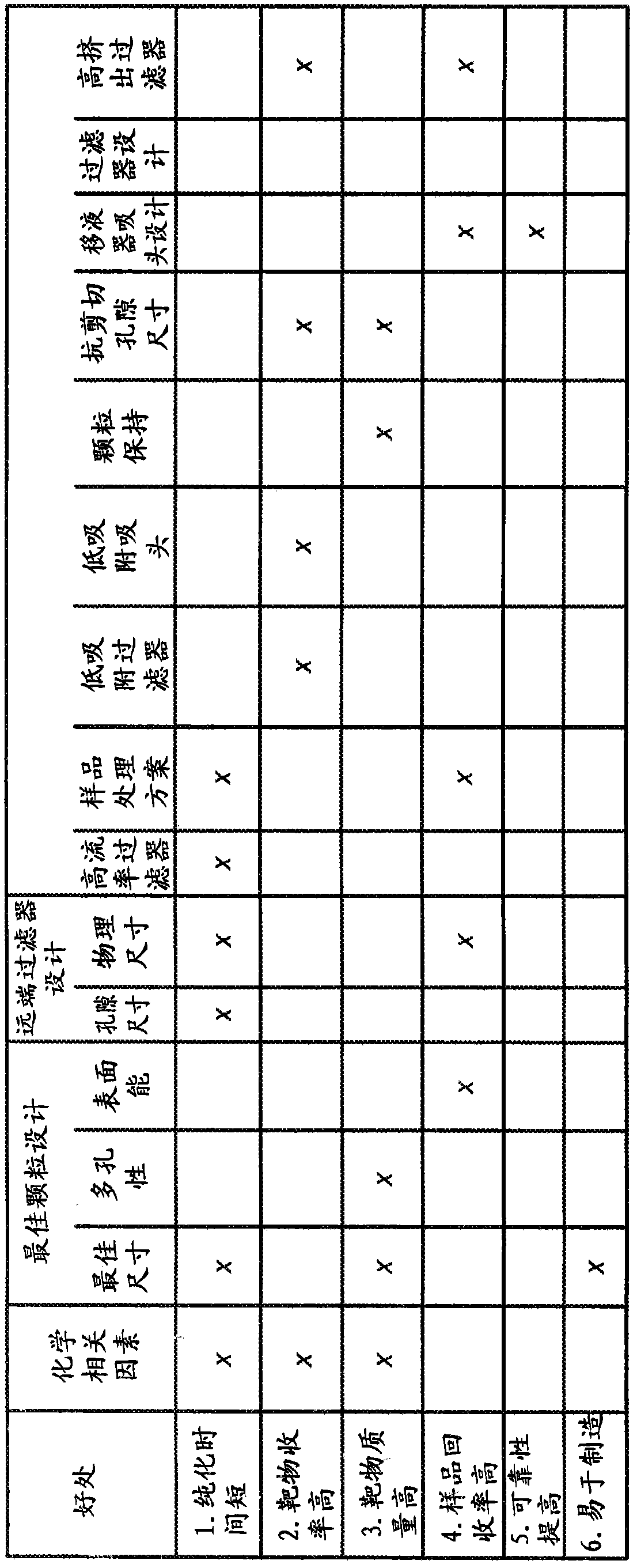
[0516] This example describes an improved pipette filter design that can be used in a fluid sample purification system. Specific features of this filter include: very low fluid flow resistance, consistent fluid flow resistance, uniform pore size, low sample retention and low cost. Unlike prior art fluid sample purification systems, embodiments of the present invention fluid sample purification system with this filter design have components within the pipette tip ...

Embodiment 2

[0534] 6.2 Example 2: Fluid sample purification system comprising pipette tips with mixing (reaction) chambers

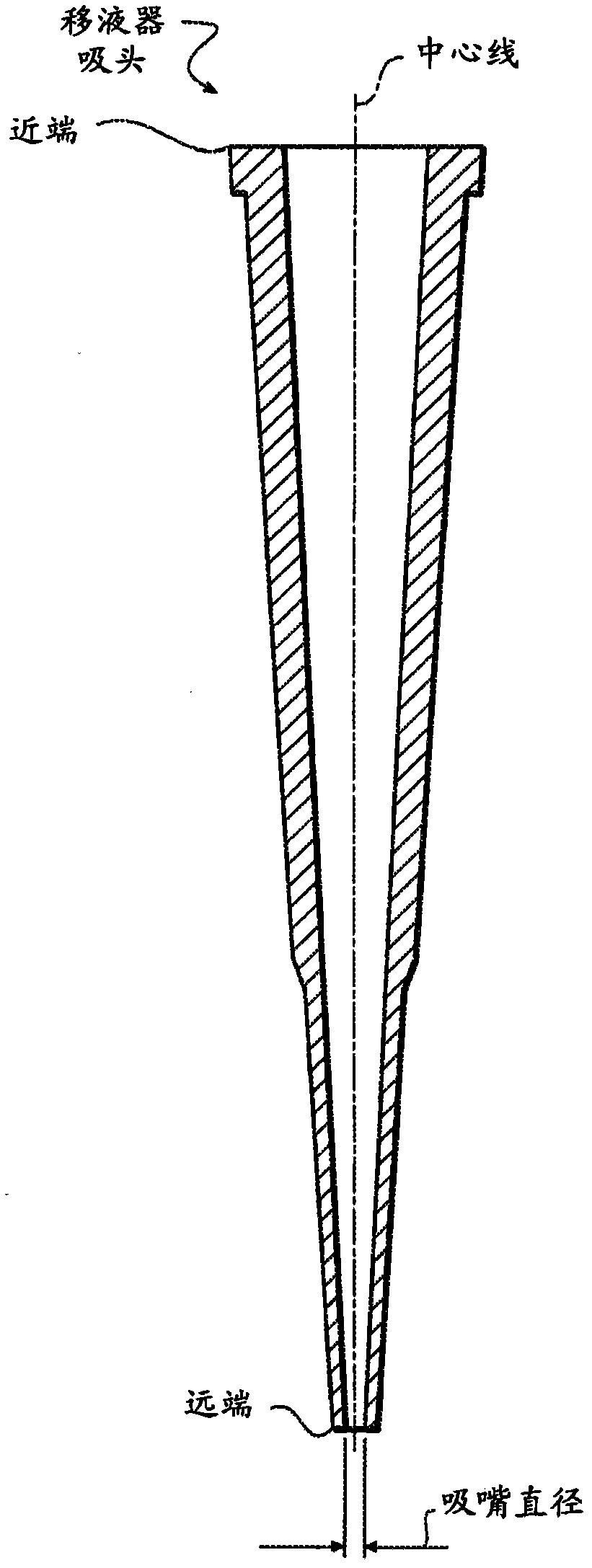
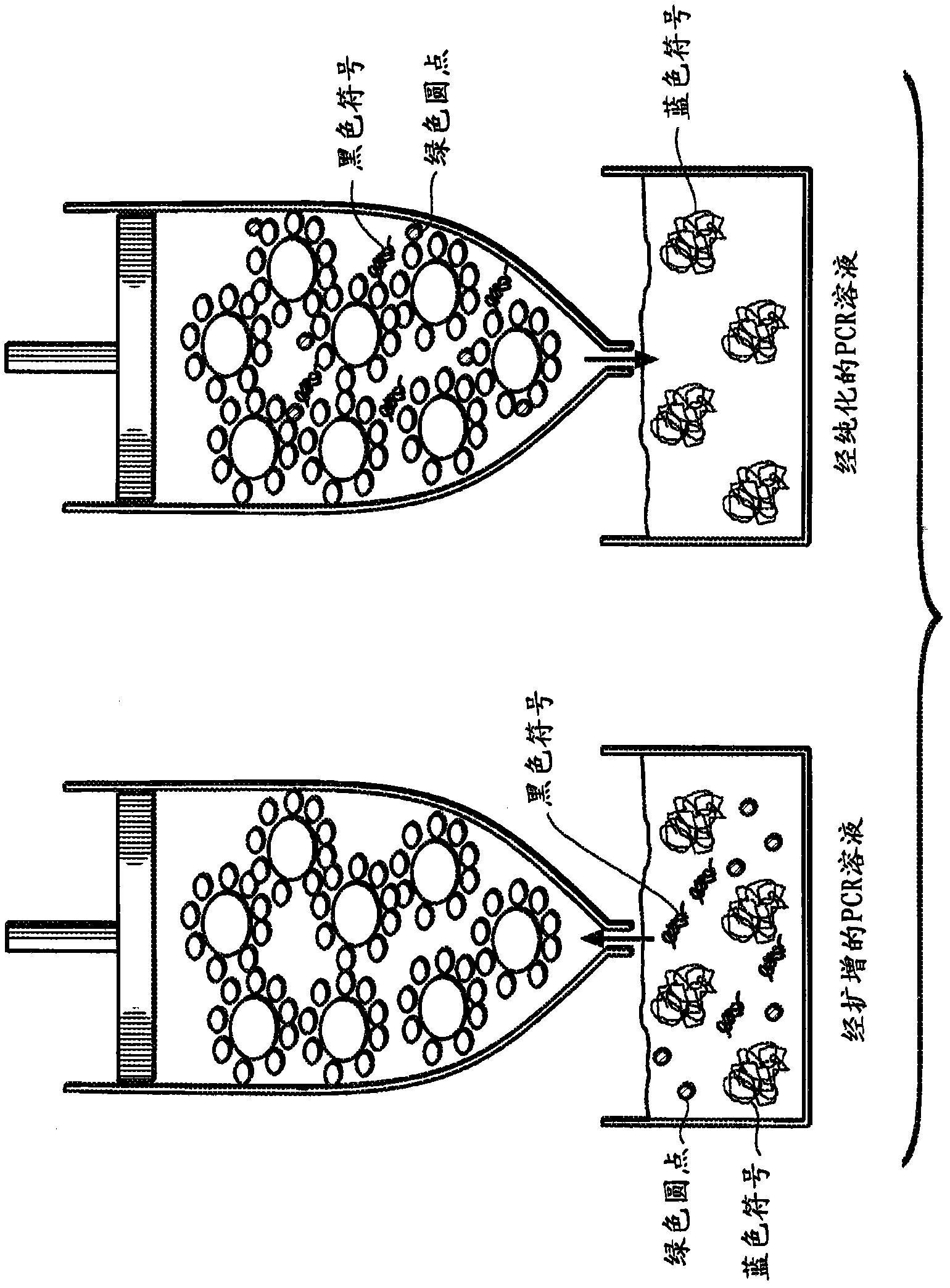
[0535] This example describes another embodiment of a fluid sample purification system comprising a pipette tip with a different fluid mixing (or reaction) chamber design than described above. The mixing (reaction) chamber has a low slenderness ratio, a design that allows for a more efficient interaction between the aspirated / dispensed sample and the adsorbent material. Figure 40b Shown containing loosely packed particles (not shown but with figure 2 similar) and distal particle holder B and designed pipette tip A with a mixing chamber C of low height L. ( Figure 40a A typical prior art pipette tip configuration is shown). There is a transition zone from the nozzle diameter d to the pipette inner diameter D over a very short distance. Angle β is preferably about thirty degrees to help ensure an even transition of fluid flow from the pipette nozzle to the larg...

Embodiment 3

[0539] 6.3 Example 3: Fluid Sample Purification System Containing Pipette Tips with Minimal Internal Air Volume

[0540] This example describes another embodiment of a fluid sample purification system comprising a pipette tip with internally positioned pistons to minimize internal volume and generate high fluid sample aspiration and dispensing pressures.

[0541] The present fluid sample purification system embodiment comprises a pipette tip and a piston providing a minimum air volume within the pipette tip. Since the air contained within a pipette tip is a compressible fluid, the more air in the tip, the lower the pressure or vacuum that can be created within the pipette tip for a given displacement of the pipette piston. Since the pressure differential between the inside and outside of the pipette tip is the driving force for moving liquid into and out of the pipette tip, smaller pressure or vacuum differentials will result in lower sample flow rates. The sample flow rate i...


PUM

PropertyMeasurementUnit
sizeaaaaaaaaaa
sizeaaaaaaaaaa
diameteraaaaaaaaaa

Abstract

Fluid sample purification systems and methods are provided for isolating molecules of interest in a fluid sample. The fluid sample purification system has a housing with a distal end and distal opening adapted for the passage of a fluid and a proximal end and proximal opening adapted for passage of a fluid. A distal retainer is located inside the housing and above the distal opening. A proximal retainer is located inside the housing between the distal retainer and the proximal opening, or is located adjacent to, in contact with, or over the proximal opening. The system also comprises adsorption material, e.g., functionalized particles, inside the housing and confined between the distal retainer and the proximal retainer. The adsorption material adsorbs undesirable material while simultaneously rejecting desirable materials.; Methods are also provided for isolating molecules of interest using the fluid sample purification system.

Description

[0001] Cross References to Related Applications [0002] This application claims co-pending U.S. Provisional Patent Application Serial No. 61 / 152,680, filed February 14, 2009, entitled "Devices for Purifying Biological Materials" and filed December 28, 2009, entitled "System and Methods for Priority and benefit of co-pending U.S. Provisional Patent Application Serial No. 61 / 290,333 for Purifying Biological Materials, both filed by Jeffrey L. Helfer and Rhiannon R. Gaborski, each of which was adopted by Citations are incorporated herein in their entirety. [0003] Statement Regarding Federally Sponsored Research or Development [0004] This invention was made with government support from the National Institutes of Health, STTR grant numbers R41RR024968-01 and 2R42RR024968-02. The government has certain rights in this invention. technical field [0005] The present invention relates to systems and methods for purifying fluids. The present invention also relates to systems an...

Claims


Application Information

Patent Timeline
Patent Type & Authority Applications(China)
IPC IPC(8): C12M1/00
CPCB01L2300/0681B01L3/0275B01L2200/0631G01N1/4005C12N15/1003G01N2035/1053G01N2001/4016B01L2300/0609G01N1/34G01N1/405
Inventor 杰弗里·L·赫尔飞李安农·R·加布雷斯基莫里斯·A·希达尔
Owner DIFFINITY GENOMICS
Why Eureka
Try Eureka