

System and method for processing residual sludge decrement synchronous denitrification
A technology for excess sludge and treatment methods, applied in biological sludge treatment, anaerobic digestion treatment, etc., can solve the increased load and cost of sludge treatment, barriers to popularization and application of internal carbon source development technology, and biochemical availability Other issues such as unclear impacts, to achieve the effect of improving stability and handling performance, saving construction and renovation costs, and strong scalability
- Summary
- Abstract
- Description
- Claims
- Application Information
AI Technical Summary
Problems solved by technology
Method used
Image

Examples
Embodiment Construction
[0040] The present invention will be described in further detail below in conjunction with the accompanying drawings and embodiments.
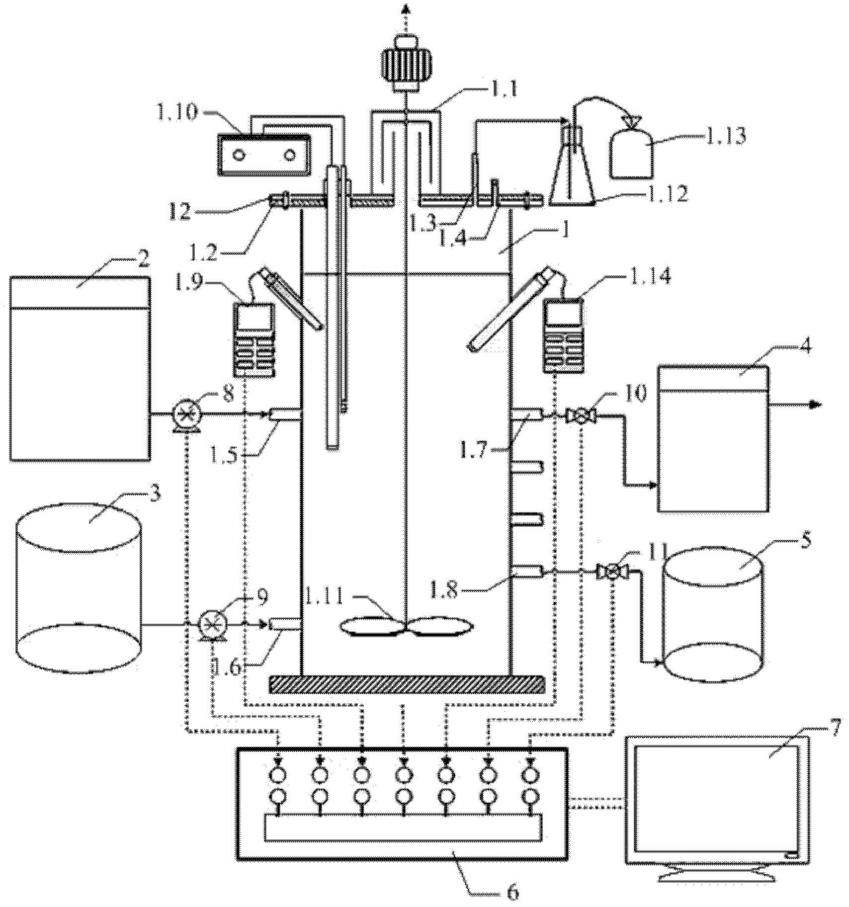
[0041] As shown in Figures 1 to 1, the present invention provides an optimal treatment system for synchronous denitrification and denitrification of excess sludge, including a control device 6, a main reactor 1, a raw water injection mechanism, a sludge injection mechanism, a drainage mechanism, and a sludge discharge mechanism. Mechanism and computer 7, wherein, the control device 6 is respectively connected with the raw water injection mechanism, the sludge injection mechanism drainage mechanism and the sludge discharge mechanism with the computer 7, and the raw water injection mechanism and the sludge injection mechanism are connected with the injection end of the main reactor 1 , the drain mechanism and the sludge discharge mechanism communicate with the discharge end of the main reactor 1 . Wherein, the main reactor 1 is a cylindrical air...
PUM
 Abstract
Description
Claims
Application Information