Charge air cooling device for a combustion engine

A technology of charge air cooling and charge air, applied to internal combustion piston engines, combustion engines, mechanical equipment, etc., can solve the problems of charge air coolers restricting charge air flexibility and huge integration costs.

Inactive Publication Date: 2012-05-09
GM GLOBAL TECH OPERATIONS LLC
View PDF1 Cites 3 Cited by
  • Summary
  • Abstract
  • Description
  • Claims
  • Application Information

AI Technical Summary

Problems solved by technology

[0005] The known geometry of the charge air cooler sometimes significantly limits the flexibility of charge air conduction between the compressor or supercharger and the air supply on the engine side
If a fluid-cooled heat exchanger is installed as a charge air cooler instead of an air-to-air heat exchanger, this entails significant integration costs

Method used


Image

  • Charge air cooling device for a combustion engine
  • Charge air cooling device for a combustion engine
  • Charge air cooling device for a combustion engine

Examples


Embodiment Construction

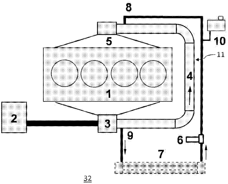
[0031] figure 1 The charge air cooling system shown in has a cooling circuit, in particular for cooling the charge air, which in this embodiment consists of a coaxial tube heat exchanger 11, a coolant outlet 9, a charge air cooler 7. A coolant pump 6, a coolant compensating container 10 and a coolant inlet 8 leading to a coaxial tube heat exchanger 11 are formed. A coaxial tube heat exchanger 11 extends between the compressor or supercharger 3 and the intake manifold 5 of the internal combustion engine 1 . The entire combustion air conduction path between the supercharger 3 and the intake manifold 5 here forms the cooling path 4 of the heat exchanger 11 .

[0032] In this connection, it is provided that the charge air guide provided downstream of the supercharger 3 and upstream of the internal combustion engine 1 is designed almost entirely as a cooling path of the coaxial tube heat exchanger 11 . As a result, the cooling efficiency of the intercooler can be increased, and m...


PUM


Abstract

The present invention relates to a charge air cooling device for a combustion engine. The cooling device comprises a first heat exchanger 11 for transmitting thermal energy of a charge airflow to a coolant 30 and a second heat exchanger 7 for radiating thermal energy of the coolant 30 into the surrounding environment. The first heat exchanger 11 is designed as a coaxial tube heat exchanger 11 such that at least part of the first heat exchanger is coaxial with the charge air flow and is such that the coaxial tube heat exchanger directly connects a compressor 3 to the engine 1.

Description

technical field [0001] The invention relates to a charge air cooling device for an internal combustion engine in order to cool the combustion air compressed by a compressor or a supercharger before being fed into the combustion chamber of the engine. Background technique [0002] In a charge-charged internal combustion engine, the combustion air supplied to the engine can be cooled by means of a charge air cooler. Cooling the combustion air makes it possible to increase its density and thus deliver an increased gas quantity to the engine while maintaining equal pressure. In this way, the combustion process, in particular the efficiency of the engine, can be optimized or increased. [0003] Commonly used charge air coolers are mostly designed as air-to-air heat exchangers. Furthermore, known air-to-air charge-air heat exchangers are generally located in the engine compartment of automobiles, since the cooled combustion air discharged from the charge-air cooler should have a...

Claims


Application Information

Patent Timeline
Patent Type & Authority Applications(China)
IPC IPC(8): F02B29/04
CPCY02T10/146F02B29/0443F28D7/106F28D7/14Y02T10/12Y10T29/49359F02B29/0425F02B29/045
Inventor K-O.皮特什L.塞波尔德I.拉扎里迪斯U.诺布劳克
Owner GM GLOBAL TECH OPERATIONS LLC
Why Eureka
Try Eureka