Method for operating internal combustion engine

An internal combustion engine and sensor technology, applied in mechanical equipment, engine control, fuel injection control, etc., can solve the problem of inability to identify the failure of the high-pressure generating device, and achieve the effect of preventing engine flameout

Inactive Publication Date: 2012-05-09
ROBERT BOSCH GMBH
View PDF6 Cites 0 Cited by
  • Summary
  • Abstract
  • Description
  • Claims
  • Application Information

AI Technical Summary

Problems solved by technology

If the pressure detector fails, this failure of the high pressure generating device cannot be identified

Method used


Image

  • Method for operating internal combustion engine
  • Method for operating internal combustion engine

Examples


Embodiment Construction

[0019] The invention is schematically shown in the drawing with the aid of an embodiment and will be explained in more detail below with reference to the drawing.

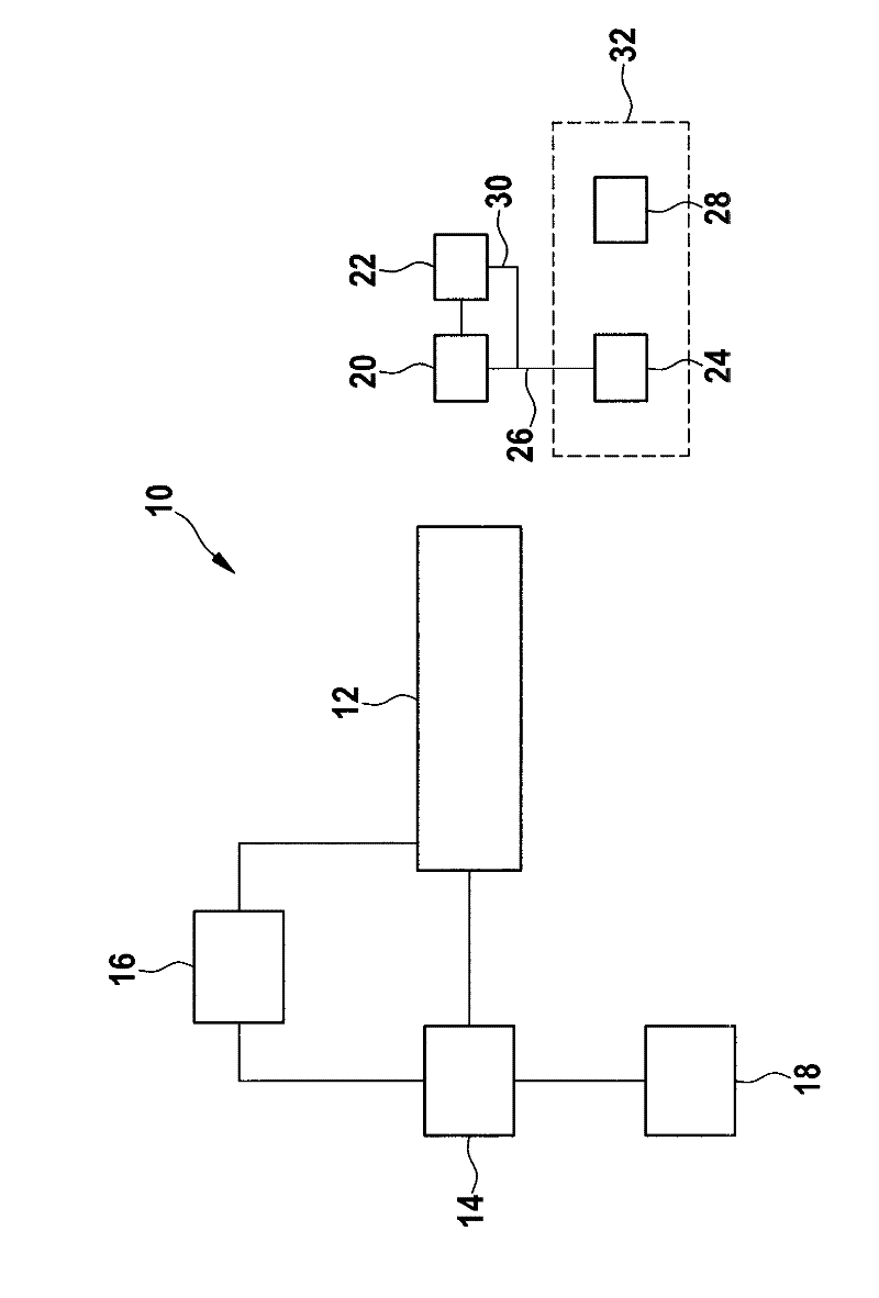
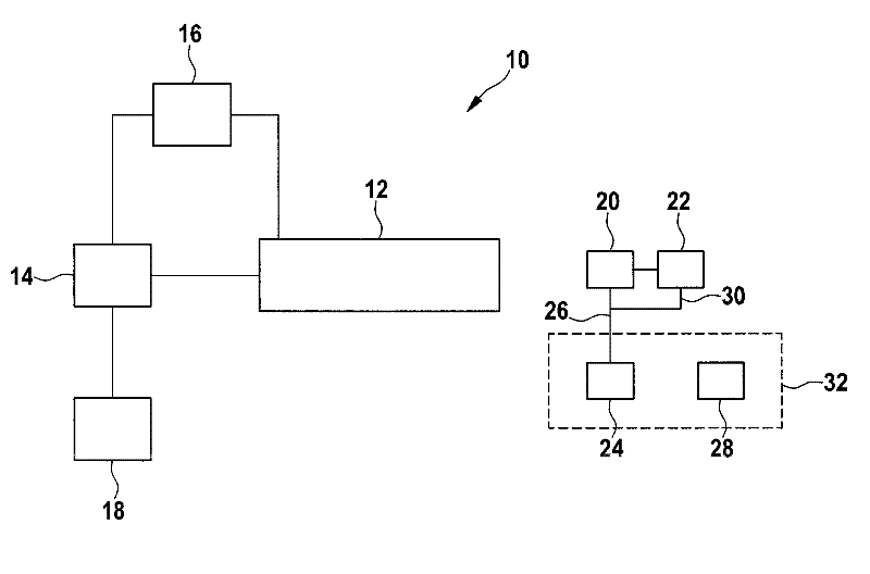
[0020] There is shown an internal combustion engine 10 with a pressure accumulator or rail 12 into which fuel is entered by means of a high pressure pump 14 and held there for direct injection into a combustion chamber (not shown). The pressure in the pressure accumulator 12 is adjusted by means of a pressure regulating device 16 . Furthermore, the drawing shows a prefeed pump 18 and a lambda sensor 20 with a regulator 22 .

[0021] If a fault then occurs in the high-pressure pump 14 or the pressure regulating device 16 , the pressure in the pressure accumulator 12 drops. This was not directly noticed because no pressure detectors were installed. Since the selected injection time is adapted to the pressure supplied jointly by the prefeed pump 18 and the high-pressure pump 14 , this results in too little petrol in...


PUM


Abstract

The method involves using pressure accumulator or rails (12) with a direct injection, with which an output signal (26) of lambda probe (20) is evaluated. The lambda probe signal monitors engine speed to detect a malfunction.

Description

technical field [0001] The invention relates to a method for operating an internal combustion engine and a device for carrying out the method. Background technique [0002] Direct injection engines are used in automobiles. Direct injection refers to the method of fuel injection for diesel and gasoline engines in which fuel is injected directly into the combustion chamber via a pressure accumulator or rail. Here, the air-fuel mixture is formed directly in the combustion chamber. In direct injection, the fuel is injected directly into the combustion chamber at high pressure using a special injection valve. The precise metering, preparation and distribution of air and fuel for each individual combustion stroke results in low system consumption and low emissions. [0003] So-called lambda sensors are used in direct injection engines. A lambda sensor is a detector which measures the current residual oxygen content in the exhaust gas of an internal combustion engine. From thi...

Claims


Application Information

Patent Timeline
Patent Type & Authority Applications(China)
IPC IPC(8): F02D41/22F02D41/40
CPCF02D41/1456F02D2041/226F02D2200/1012F02D41/1498F02D41/221F02D41/3863
Inventor A. 罗特P. 申克
Owner ROBERT BOSCH GMBH
Why Eureka
Try Eureka