Gas-to-gas heat exchanger and waste gas incinerator integrating same

A technology of exchangers and incinerators, applied in the direction of incinerators, indirect heat exchangers, heat exchanger types, etc., can solve the problems of poor heat exchange efficiency, difficult cleaning and maintenance, etc.

Active Publication Date: 2012-05-09
JG ENVIRONMENTAL TECH +1
View PDF6 Cites 4 Cited by
  • Summary
  • Abstract
  • Description
  • Claims
  • Application Information

AI Technical Summary

Problems solved by technology

[0007] The main purpose of the present invention is to overcome the above-mentioned shortcomings of existing products, and provide a gas-to-gas heat exchanger and a waste gas incinerator integrating the heat exchanger, which can solve the problem of poor heat exchange efficiency and relatively difficult cleaning and maintenance in the prior art. No problem, but has the effect of improving heat exchange efficiency and easy cleaning and maintenance

Method used


Image

  • Gas-to-gas heat exchanger and waste gas incinerator integrating same
  • Gas-to-gas heat exchanger and waste gas incinerator integrating same
  • Gas-to-gas heat exchanger and waste gas incinerator integrating same

Examples


Embodiment Construction

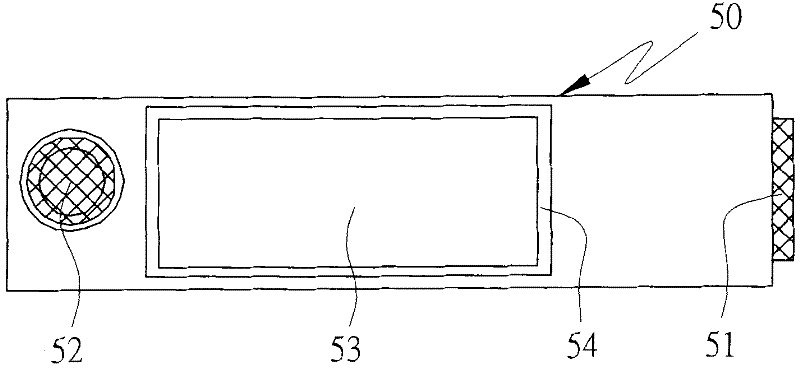
[0041] First, see Figure 3 to Figure 5 As shown, the first embodiment of the air-to-air heat exchanger of the present invention includes: an outer box body 50, an inner hanging body 60a and a thermal insulation layer 80; wherein: the two ends of the outer box body 50 form There is a first gas inlet 51 and a first gas outlet 52 , and an insertion port 53 is formed at the top relative to the inner hanging body 60 a.

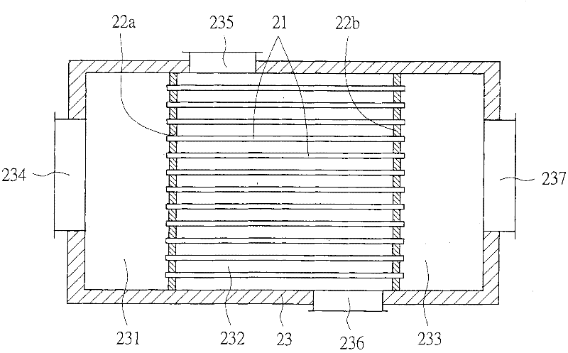
[0042] The inner hanging body 60a is provided with connecting flanges 64, 54 opposite to the insertion opening 53, so that the inner hanging body 60a is suspended and positioned inside the outer box body 50 through the insertion opening 53; The inner hanging body 60a has an upper box body 61 and a lower box body 62, and the two ends of the air guide tube bundle 63 are welded on the bottom plate of the upper box body 61 and the top plate of the lower box body 62, and the inside of the upper box body 61 is made of a partition plate. 612 separates the second type ga...


PUM


Abstract

The invention discloses a gas-to-gas heat exchanger and a waste gas incinerator integrating the same. The gas-to-gas heat exchanger comprises an outer tank body, an inner hanging and hoisting body and an insulation layer, wherein the outer box body is provided with a first gas inlet, a gas outlet and an imbedding hole; the inner hanging and hoisting body is arranged in the outer box body and comprises an upper box body, a lower box body and a gas guide pipe bundle, the lower box body is internally provided with a rotary chamber, a second-class gas inlet chamber of the upper box body is provided with a second-class gas inlet, a second-class gas outlet chamber of the upper box body is provided with a second-class gas outlet; and the insulation layer is arranged in the outer box body. The waste gas incinerator integrating the gas-to-gas heat exchanger comprises an outer tank body, an inner hanging and hoisting body, an insulation layer and a furnace end, wherein the outer box body is provided with a first gas inlet, a gas outlet and an imbedding hole; the inner hanging and hoisting body is arranged in the outer box body and comprises an upper box body, a lower box body and a gas guide pipe bundle, the lower box body is internally provided with a rotary chamber, a second-class gas inlet chamber of the upper box body is provided with a second-class gas inlet, a second-class gas outlet chamber of the upper box body is provided with a second-class gas outlet; the insulation layer is arranged in the outer box body; and the furnace end is arranged in an outer box body combustion chamber, and a combustion chamber gas inlet and a combustion chamber gas outlet are connected with the second-class gas outlet and a first-class gas inlet. The invention has the advantages of high heat exchange efficiency and easiness in cleanness and maintenance.

Description

technical field [0001] The invention relates to a method of allowing the second gas flow to flow through the air-guiding tube bundle multiple times through rotation, so as to perform long-term heat exchange with the first gas flowing outside the air-guiding tube bundle, and make the gas-guiding tube bundle adopt The hanging method is used for positioning, and it is convenient to lift out the air-to-air heat exchanger and the waste gas incinerator integrating the heat exchanger for cleaning and maintenance work and eliminating thermal strain problems. Background technique [0002] Organic solvents that are widely used in life and production are easily volatile into gases, so they are also called Volatile Organic Compounds (VOCs), and most VOCs are toxic to the human body and must be treated; among them, the incineration method is VOCs waste gas One of the treatment methods, the VOCs removal rate can reach more than 99% under appropriate conditions, and the products after comb...

Claims


Application Information

Patent Timeline
IPC IPC(8): F28D1/04F23G7/06
Inventor 张丰堂
Owner JG ENVIRONMENTAL TECH
Why Eureka
Try Eureka