Roller bearing cage and method of producing the same

a technology of roller bearings and cages, which is applied in the direction of roller bearings, connecting rod bearings, mechanical devices, etc., can solve the problems of inconvenient production, high labor intensity, and inability to finish the cage blank in the desired contour, so as to save the row stock of material, improve the efficiency of production, and save production costs

Active Publication Date: 2007-08-07
NIPPON THOMPSON
View PDF6 Cites 6 Cited by
  • Summary
  • Abstract
  • Description
  • Claims
  • Application Information

AI Technical Summary

Benefits of technology

[0008]The present invention has for its primary object to resolve the major problems as stated earlier, and to make a further development of the roller bearing cage disclosed in the senior application of common assignment, which is recited earlier in “background of the invention”, to provide a roller bearing cage well applicable to the high-compression, high-speed engine, with more inexpensive production costs. The constructional features of the present invention reside in a turning operation on the lathe at the initial step to generate a cage blank, and a configuration of the cage with inside retainer projections unique in construction finished using a rolling operation other than the turning operation. More particularly the present invention is to provide a roller bearing cage favorable for the bearings, which are needed to stand up to the harsh conditions imposed by advanced high-compression, high-speed engine, and also to provide a production method of a roller bearing cage with using a rolling operation, which is substantially more friendly to the environment because of conserving row stock of material while cutting hours to make the desired bearing cage, and also because of the absence of the formation of chips. Thus, the production method according to the present invention makes it possible to provide inexpensively the desired roller bearing cage from basic minimum quantity of row material.
[0015]The present invention is further concerned with a method of producing a roller bearing cage comprising steps of; shearing a tubular material into a ring-like blank; processing the ring-like blank by rolling operation into a rolled product of cage contour where there is formed a circular inside recess of semicircular contour in transverse section in axial direction of the cage; working the rolled product by punching operation so as to have more than one pocket for receiving the roller therein, which are spaced circularly away from one another; further working the punched product with pockets into a formed product in which raised ridges are made on the pillars between two adjoining pockets preparatory to the inside retainer lips to keep the rollers against falling away from the cage; processing the formed product by turning operation to face flat surfaces on the axially opposite sides of the formed product, yielding a turned product; heating the turned product into a heat-treated product high in durability; further working the heat-treated product by turning operation to finish a circular outside surface thereof into a final form of a prescribed outside circumferential dimension; and processing the turned product of the prescribed outside circumferential dimension by surface treatment to provide a finished cage enhanced in durability.
[0017]With the roller bearing cage constructed as stated earlier, the circular inside recess made around the circular inside surface of the cage is formed to have the concaved surface that is easier to work it by any one of the turning operation and the rolling operation, even with inexpensive production cost. The roller bearing cage of the present invention is expected to display desired performance tolerant to the high-speed engines when installed in the rod “big-end” of the connecting rod of the engine. The roller bearing cage of the present invention is envisaged making the surface-to-surface contact stress more uniform across the overall circular outside surface of the cage, and also rendering the cage less in weight to reduce the surface-to-surface contact stress that might be exerted on the cage. Since the rollers are kept in the cage with the outside and inside retainer lips for free rotation, but against falling away out of the cage whether inside or outside, the roller bearing cage making sure of keeping the rollers against falling away is much easier to handle it upon installation of the roller bearing cage into mating connecting rod in the engine. The roller bearing cage, as undergoing revolving force as well as centrifugal force, is born or guided predominantly on the circular outside surface of the cage. The cage recessed around the circular inside surface thereof to have the concaved surface helps stave off any locally lopsided surface-to-surface contact stress, which might otherwise occur on the circular outside surface of the cage, and also render the weight of the cage as small as possible, lessening the surface-to-surface contact stress imparted on the cage. As a result, the roller bearing cage of the present invention is more tolerant to the high revolution of the engine, compared with the prior roller bearing cage.
[0018]The roller bearing cage in which the cage is processed with using a rolling operation present invention may be provided inexpensively from basic minimum quantity of row material, compared with the cage worked on the lathes by the turning operation. The rolling operation where the circular surface inside the cage blank is subjected to the compressive working by rolls is preferable to ensure the strength and stiffness of the cage, and substantially more friendly to the environment because of the absence of the formation of chips. With the roller bearing cage constructed as stated earlier, the circular inside surface of the cage is designed into the specific contour, which would be worked easily by the rolling operation, more particular, the concaved surface semicircular in transverse section in the axial direction of the cage. Moreover, the inside retainer lips lying in flush with circular inside surface of the cage are preferable for the rolling operation and also result in such construction that they are hard to make any engagement with their associated rollers, which might worsen the engine performance.
[0019]According to the present invention, consequently, the roller bearing cage improved in performances including stiffness, strength, and so on of the cage itself may be provided from basic minimum quantity of row material, with using the working operation that is substantially more friendly to the environment and more expensively because of conserving row stock of material while cutting hours to make the desired bearing cage, and also because of the absence of the formation of chips. In forming the inside retainer lips to the cage for the roller bearing cage according to the present invention, inside raised ridges are first formed simultaneously with the rolling operation and, then, the inside raised ridges are easily finished by the pressing operation into the inside lips that are flush with the circular inside surface of the cage. The construction in which the inside retainer lips are made flush with the circular inside surface of the cage helps render the rollers harder to make any engagement with the inside retainer lips, compared with the prior roller bearing cage. The constructional feature that the rollers are hard to make engagement with the inside retainer lips results in keeping the cage against any occurrence of seizing during high revolution of the engines, realizing improvement in engine performance.

Problems solved by technology

With the prior roller bearing cage made in a configuration resembling any gate in cross section where a ring-like blank is turned on lathe to cut a circular inside surface of the blank into roughly U-shape in cross section, nevertheless, as the cage would sometime made uneven in thickness, the surface-to-surface contact stress of the bearing cage against the circular surface inside the big-end bore trends to result in any harsh condition during installation in the rod “big-end” of the connecting rod in engines.
Further, the turning operation carried out on the lathes to finish the cage blank into the desired contour would take substantial time and effort, while involving cutting much excess metal, in the form of chips, from the cage blank.
This means that the prior manufacturing process for the roller bearing cage produces in vain much metal waste in the form of chips or debris, which should be disposed properly.
Besides, the prior cages constructed as stated earlier, because of their configuration like any gate having U-shape much bumpy with many angular corners, is very tough to machine them by the turning operation on the cage blank.
The cage construction as recited above has an adverse tendency to cause somewhat increased surface-to-surface contact stress that might take place between the bearing cage and the circular inside surface in the big-end bore of the connecting rod.
In addition, the prior needle bearing cage constructed as stated earlier is also tough to produce it by the turning operation on the cage blank, because the circular inside surface is made in the angularly bumpy configuration, which consists of the inside surfaces of the middles small in thickness, and other inside surfaces of the axially opposite sides merging together with the middles through ramps inclining towards the axial center of the cage.
The prior needle bearing cage is further unsuited to handle it since the cage has no construction favorable for positively retain the associated needles.
The production method of the roller beating cage recited earlier using the rolling operations to manufacture the race ring, because of requiring highly skilled effort of rolling operation, is hard to work the cage with high accuracy in roundness, concentricity, and so on.

Method used


Image

  • Roller bearing cage and method of producing the same
  • Roller bearing cage and method of producing the same
  • Roller bearing cage and method of producing the same

Examples


Embodiment Construction

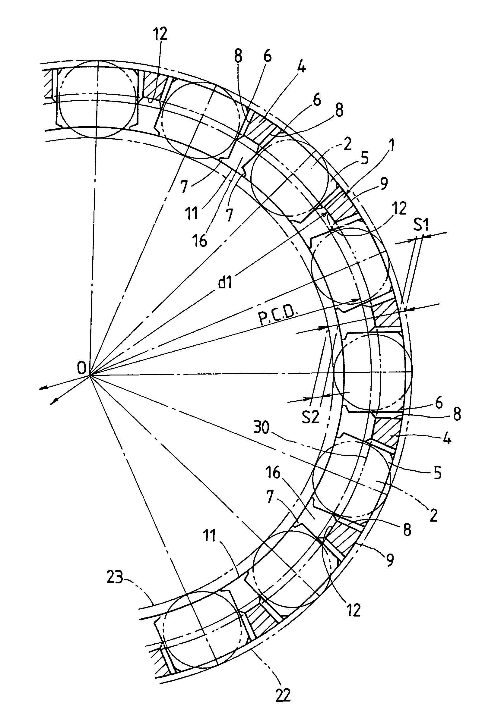
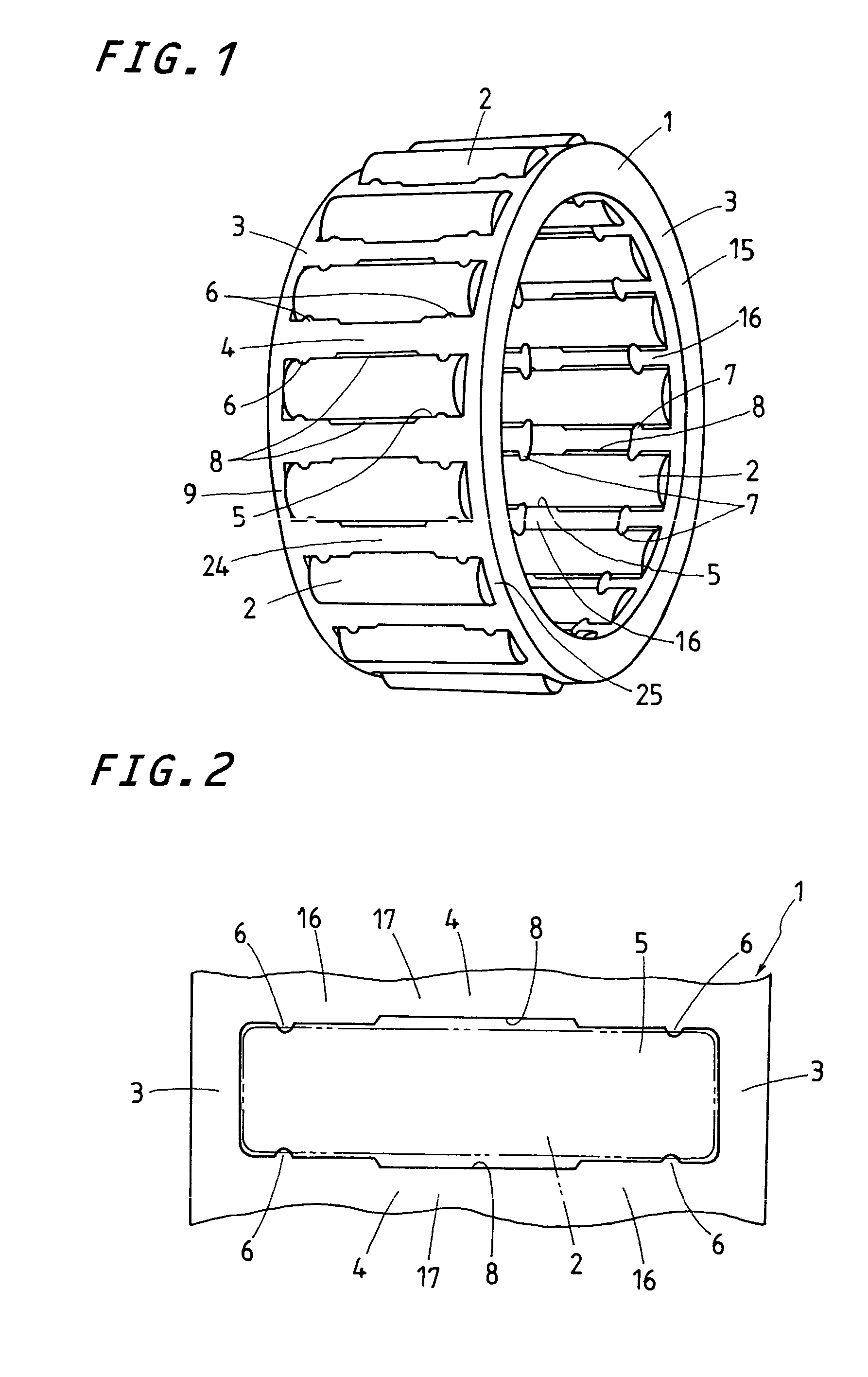
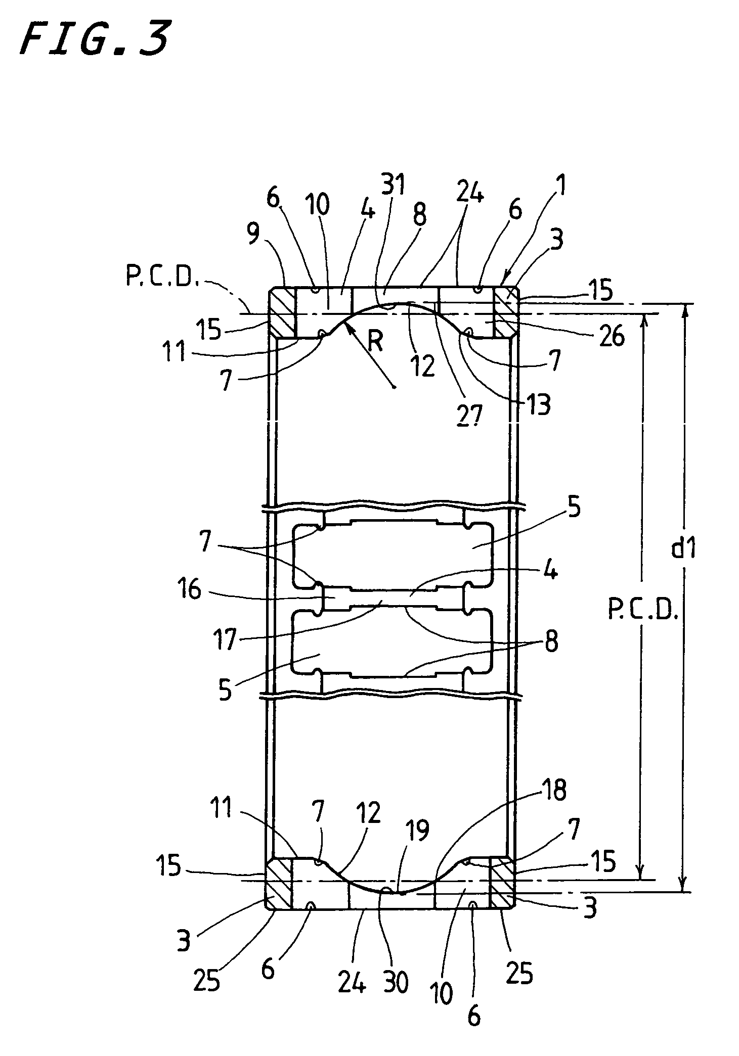
[0036]A roller bearing cage and a method of producing the same according to the present invention will be explained below with reference to the accompanying drawings. The roller bearing cage according to the present invention discussed later is adapted for use in machines such as engines, and so on, especially in a rod “big end” of the connecting rod in the engine. Referring to FIGS. 1 to 4, a roller bearing cage of the present invention will be described below in detail.

[0037]The roller bearing cage of the present invention is mainly comprised of a cage 1 and rollers 2, commonly referred to as “needle”, which fit in the cage 1. The cage is composed of a pair of annular members 3 spaced away from one another in axial direction with extended circularly in parallel with one another, and a plurality of pillars 4 made integral with the annular members 3 and positioned at regular intervals around the circular surfaces of the annular members 3 to form pockets 5 between any two adjacent pi...


PUM


Abstract

A roller bearing cage is disclosed, which is provided inexpensively from basic minimum quantity of row material. The roller bearing cage is made with a production method using rolling operations, which is the absence of the formation of chips, while ensuring the strength and stiffness of the cage. A circular inside surface of the cage is made to give an advantage to the rolling operations. The circular inside surface is circularly recessed to have a concaved surface of just one radius of curvature R. A diametral dimension across diametrically opposing bottoms of the circular recess is made larger than the pitch circle distance P.C.D. Pillars of the cage have inside retainer lips, which are hard to make any engagement with their associated rollers, which might worsen the engine performance.

Description

FIELD OF THE INVENTION[0001]The present invention relates to a roller bearing cage serving as parts for engines. Still more particularly, the invention is concerned with a roller bearing cage suitable for use in a larger end, commonly referred to as rod “big end”, of a connecting rod in an engine and a method of producing the same.BACKGROUND OF THE INVENTION[0002]There have been conventionally developed many types of roller bearing cages usable in the rod “big end” of the connecting rod in the engines. An example of conventional bearing cages as stated earlier is disclosed in, for example Japanese Patent Laid-Open No.1996-219149. The prior roller bearing cage is made in a configuration resembling any gate in cross section where the circular inside surface of the roller bearing cage is recessed to form roughly U shape. The prior roller bearing cage is composed of a nearly cylindrical cage made up of axially opposite annular members and pillars integral with the annular members and po...

Claims


Application Information

Patent Timeline
Patent Type & Authority Patents(United States)
IPC IPC(8): F16C33/46F16C19/46F16C33/48
CPCF16C19/46F16C33/4629F16C9/04F16C19/463F16C2360/22
Inventor YOKOTA, YASUNORIHIDANO, KENGONAGAO, SHOUJI
Owner NIPPON THOMPSON
Why Eureka
Try Eureka