
Continuous-type cement metering device

A metering device and metering screw technology, applied in the field of metering, can solve the problems of unreasonable structure, large disturbance, large dust, etc., and achieve the effects of convenient maintenance and use, increased supply, and high metering accuracy.

Active Publication Date: 2013-12-04
JILIN PROVINCE ROAD CONSTR MASCH CO LTD
View PDF7 Cites 8 Cited by
  • Summary
  • Abstract
  • Description
  • Claims
  • Application Information

AI Technical Summary

Problems solved by technology

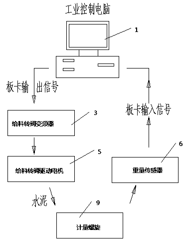
In the existing continuous cement metering device, the metering accuracy of the metering screw has exceeded ±5%, which cannot meet the standard within ±2%.
Existing continuous cement metering devices exist: 1) The self-heavy weight of the device usually weighs 300 kg, which exceeds the best range ratio in the metering system; For the pressure sensor in the device, the mechanical vibration (changes with the load) caused by its rotation number is irregular. When it responds to the electrical signal, the disturbance is particularly large. No matter which filtering method is used, it cannot be extracted. Accurate weight signals lead to serious errors beyond the range; 3) All signals of the metering part are transmitted to the industrial computer. The anti-interference ability is very poor
All in all, the existing continuous cement metering device has unreasonable structure, large volume, heavy weight, and poor metering accuracy, which cannot meet the requirements of road construction
And so far there is no literature record to overcome the above-mentioned shortcoming, solve the existing problems, the report and practical application of the continuous cement metering device of the new structure

Method used


Image

  • Continuous-type cement metering device
  • Continuous-type cement metering device
  • Continuous-type cement metering device

Examples


Embodiment Construction

[0011] The continuous cement metering device of the present invention will be further described below using the embodiments shown in the accompanying drawings.

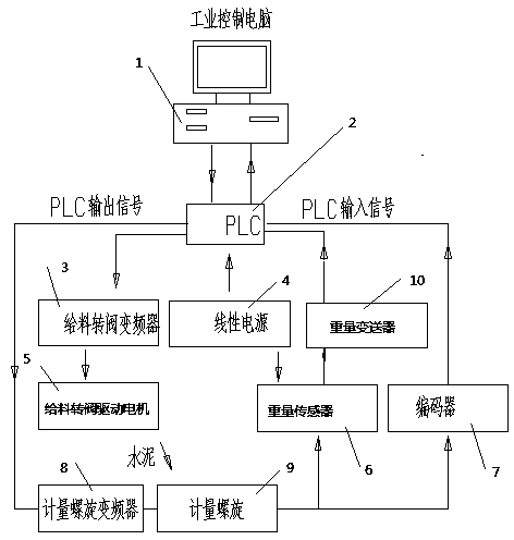
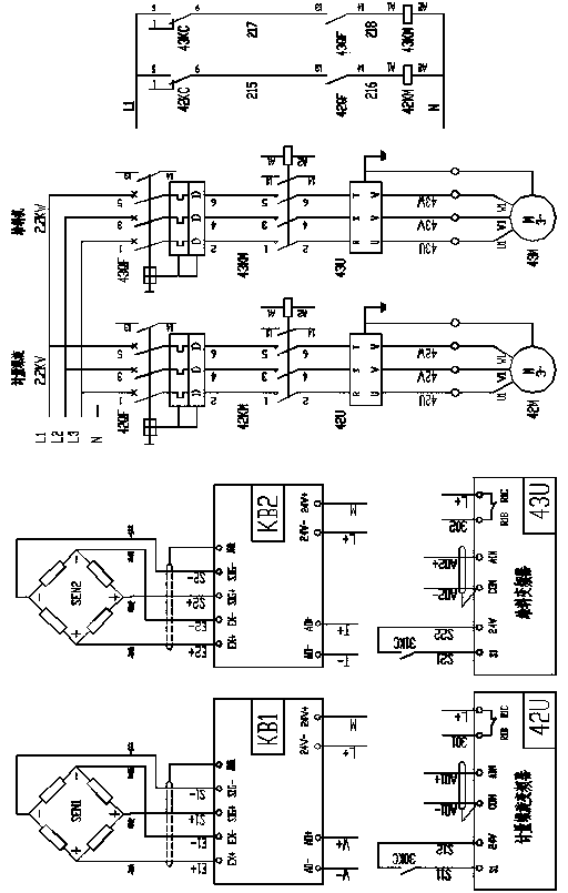
[0012] refer to Figure 2-Figure 4 , the continuous cement metering device of the present invention comprises a metering screw 9, a metering screw drive reducer 12, a feed rotary valve 11, a feed rotary valve drive motor 5, an industrial control computer 1, a feed rotary valve frequency converter 3, a weight The sensor 6, the metering screw 9 is connected with the metering screw drive reducer 12, the feeding rotary valve 11 is arranged on the feed port of the metering screw 9, the feeding rotary valve 11 is connected with the feeding rotary valve driving motor 5, and also includes a programmable Program controller PLC2, metering screw frequency converter 8, weight transmitter 10 and encoder 7, the weight sensor 6 is a pull-type weight sensor 6, and the pull-type weight sensor 6 is connected to the metering screw 9 by ...


PUM


Abstract

A continuous-type cement metering device comprises a metering screw, a metering screw driving motor, a feeding rotary valve, a feeding rotary valve driving motor, an industrial control computer, a feeding rotary valve frequency converter and a weight sensor. The continuous-type cement metering device is characterized in that the pulling-type weight sensor is connected with the meter screw in a hanging manner, the industrial control computer is connected with a programmable logic controller (PLC) electrically, the signal input end of the programmable logic controller (PLC) is connected with an encoder arranged at a shaft end of the metering screw electrically, and the signal output end of the programmable logic controller (PLC) is connected with the metering screw through a metering screw frequency converter, and is connected with the feeding rotary valve frequency converter and the feeding rotary valve driving motor electrically and sequentially. The continuous-type cement metering device has the advantages of small size, light weight, high metering accuracy, good versatility, reliable performances, and convenience in maintenance and usage, and requirements for China highways can be met.

Description

technical field [0001] The invention relates to the metering field, and relates to a continuous cement metering device. Background technique [0002] With the continuous improvement of road construction requirements in our country, the cement volume measurement method of the original stabilized soil mixing equipment has not met the requirements of batching accuracy, so as figure 1 The existing continuous cement metering system shown has been widely used in stabilized soil equipment. In the existing continuous cement metering device, the metering accuracy of the metering screw has exceeded ±5%, which cannot meet the standard requirement within ±2%. Existing continuous cement metering devices exist: 1) The self-heavy weight of the device usually weighs 300 kg, which exceeds the best range ratio in the metering system; For the pressure sensor in the device, the mechanical vibration (changes with the load) caused by its rotation number is irregular. When it responds to the ele...

Claims


Application Information

Patent Timeline
Patent Type & Authority Applications(China)
IPC IPC(8): B28C7/06G01F1/86
Inventor 孟祥彪陈世伟陈志勇王辉田永杰
Owner JILIN PROVINCE ROAD CONSTR MASCH CO LTD
Learn More