Energy feedback type linear electric motor testing and loading device

A linear motor and energy feedback technology, which is applied in the field of energy feedback linear motor test loading device, can solve the problems of non-continuous adjustment and single-direction test loading force, etc., to reduce structural deformation, improve loading accuracy, and realize energy feedback. Effect

Active Publication Date: 2012-05-09
HARBIN INST OF TECH
View PDF5 Cites 7 Cited by
  • Summary
  • Abstract
  • Description
  • Claims
  • Application Information

AI Technical Summary

Problems solved by technology

[0005] In order to solve the problem that the existing linear motor thrust loading test device can only test in one direction and the

Method used


Image

  • Energy feedback type linear electric motor testing and loading device
  • Energy feedback type linear electric motor testing and loading device
  • Energy feedback type linear electric motor testing and loading device

Examples


specific Embodiment approach 1

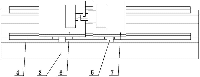
[0036] Specific implementation mode one: the following combination Figure 1 to Figure 6 Describe this embodiment, the energy feedback type linear motor test loading device described in this embodiment also includes a loading linear motor, a table body 3, a support rail 4, a tested motor sliding frame 6, a loading motor sliding frame 7, a loading linear motor controllers, force sensors and displacement sensors,

[0037] The table body 3 is a U-shaped structure, and support guide rails 4 are symmetrically arranged on the upper surfaces of the two vertical sections of the table body 3. The measuring motor sliding frame 6 is slidingly connected with the supporting rail 4 through the rail slider 5, and the loading motor sliding frame 7 is slidingly connected with the supporting rail 4 through the rail sliding block 5,

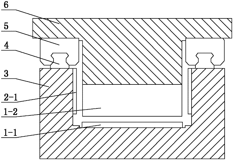
[0038] The measured linear motor stator 1-1 is fixedly installed on the inner surface of the horizontal section of the table body 3, the measured linear motor mov...

specific Embodiment approach 2

[0047] Specific implementation mode two: the following combination Figure 2 to Figure 4 Describe this embodiment. This embodiment is a further description of Embodiment 1. The loaded linear motor is a single-sided, iron-cored, moving primary linear permanent magnet synchronous motor, and the secondary is a loaded linear motor stator 2-1. The secondary is a planar structure.

[0048] The secondary symmetry of this embodiment is arranged on the inner sidewall or the outer sidewall of the two vertical sections of the table body 3 .

specific Embodiment approach 3

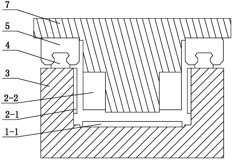
[0049] Specific implementation mode three: the following combination Figure 5 to Figure 6 Describe this embodiment. This embodiment is a further description of Embodiment 1. The loaded linear motor is a dynamic primary bilateral linear permanent magnet synchronous motor, the primary has no iron core, and the secondary is a loaded linear motor stator 2-1. The secondary is a U-shaped structure, and the secondary is symmetrically arranged on the inner wall or outer wall of the two vertical sections of the table body 3, and air gaps are formed between the primary and the two vertical sections of the U-shaped secondary.

[0050] The secondary adopts a double-stator structure, and is arranged on the inner side walls of the two vertical sections of the secondary of the U-shaped structure, forming air gaps with the primary respectively.


PUM


Abstract

The invention relates to an energy feedback type linear motor testing and loading device, which belongs to the technical field of motor testing, and solves the problem that the existing linear electric motor thrust loading and testing device can only carry out unidirectional test without continuously adjusted loading force. A stand body of the device is of a U-shaped structure, supporting guide rails are symmetrically arranged on the upper surfaces of two vertical sections of the stand body, a sliding support of a motor to be tested and a sliding support of a loading motor are respectively arranged on the supporting guide rails, the sliding support of the motor to be tested is in sliding connection with the supporting guide rails through guide rail slide blocks, the sliding support of theloading motor is in sliding connection with the supporting guide rails through guide rail slide blocks, a stator of the linear motor to be tested is fixedly arranged on the inner side surface of a horizontal section of the stand body, a rotor of the linear motor to be tested is fixedly arranged on the bottom face of the sliding support of the motor to be tested, a pair of loading linear motor stators is symmetrically arranged on the inner side walls or the outer side walls of the two vertical sections of the stand body, and a pair of loading linear motor rotors is symmetrically arranged on the sliding support of the loading motor. The energy feedback type linear motor testing and loading device, provided by the invention, is applicable to loading and testing of the linear motor.

Description

technical field [0001] The invention relates to an energy feedback type linear motor test loading device, which belongs to the technical field of motor testing. Background technique [0002] In the field of modern processing industry, many occasions such as laser cutting, high-speed grinding machines, precision lathes, machining centers, etc. require high-speed and high-precision linear motion, while traditional methods can only be obtained by means of intermediate links such as rotating motors and ball screws. Linear motion, which inevitably has disadvantages such as large inertia, large friction, and backlash. In recent years, with the advancement of linear motor technology, more and more occasions have begun to directly apply it to obtain linear motion. Due to the use of direct drive technology, linear motors have the advantages of fast speed, high acceleration, high positioning accuracy, long stroke and fast dynamic response, which just meet the requirements of high-spe...

Claims


Application Information

Patent Timeline
IPC IPC(8): G01R31/34
Inventor 寇宝泉张海林金银锡杨俊
Owner HARBIN INST OF TECH
Why Eureka
Try Eureka