High-frequency flat-panel transformer

A flat-panel transformer, high-frequency technology, applied in the direction of transformers, fixed transformers, transformer/inductor coils/windings/connections, etc., to achieve the effect of reduced volume, low loss, and reduced loss

Inactive Publication Date: 2012-05-09
AVIC NO 631 RES INST
View PDF0 Cites 19 Cited by
  • Summary
  • Abstract
  • Description
  • Claims
  • Application Information

AI Technical Summary

Problems solved by technology

[0004] The invention provides a high-frequency flat-panel transformer to solve the technical problems existing in the traditional wire-wound transformer and the existing flat-panel transformer in the background art

Method used


Image

  • High-frequency flat-panel transformer
  • High-frequency flat-panel transformer
  • High-frequency flat-panel transformer

Examples


Embodiment Construction

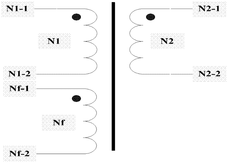
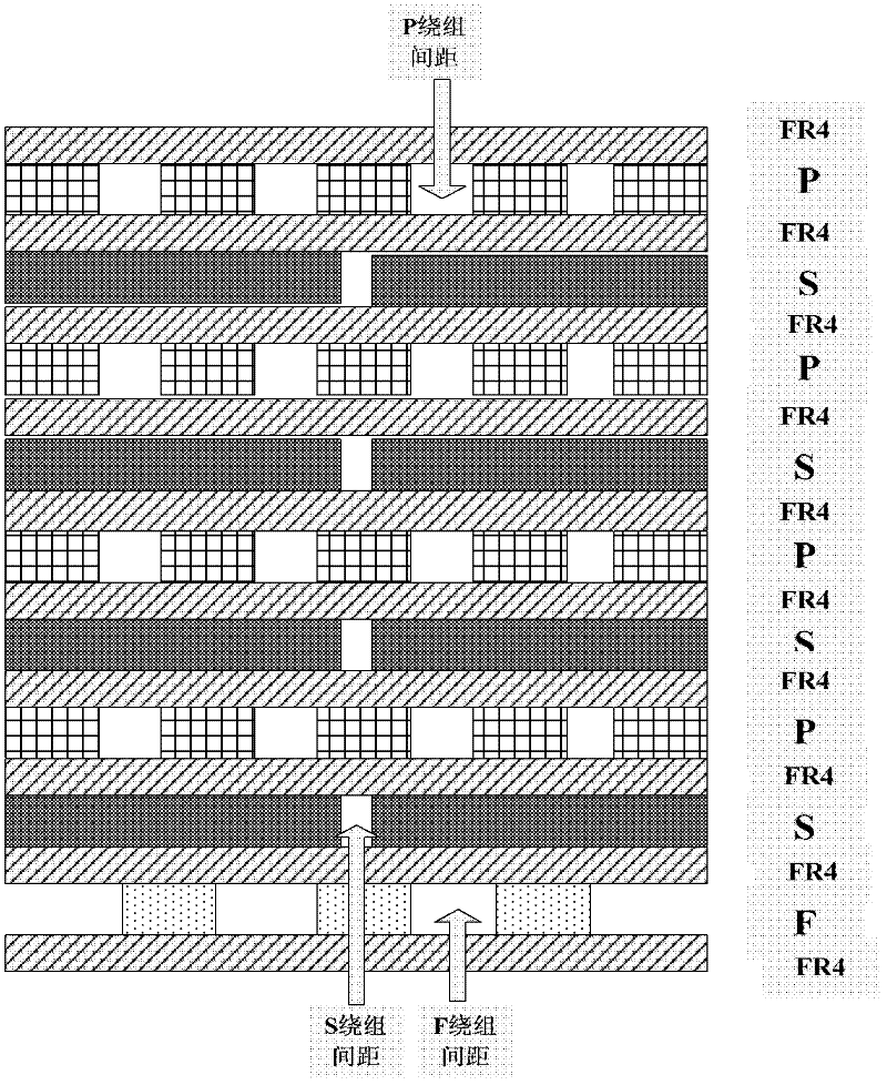
[0031] like figure 2 The schematic diagram of the flat transformer winding structure of the present invention is shown, wherein P represents the primary winding, S represents the secondary winding, F represents the auxiliary power winding (feedback winding), and FR4 is the insulating medium layer. Since each turn of winding needs to be electrically isolated, the P winding spacing, S winding spacing and F auxiliary power winding spacing are set (as indicated by the arrows in the figure). The winding adopts interlaced winding technology, and the primary side and secondary side are interleaved in layout, the purpose of which is to reduce the AC distribution parameters.

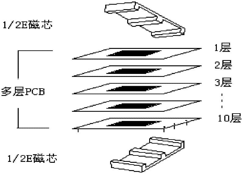
[0032] image 3 A schematic diagram of the planar transformer structure and process is given, in which the planar transformer is composed of 10-layer PCB and lead-out pins, with a thickness of 3mm. Two flat E-shaped ferrite cores (1 / 2E) are respectively assembled (with crimped) on both sides of the flat windin...


PUM


Abstract

The invention provides a high-frequency flat-panel transformer, which aims at solving the technical problems existing in the traditional winding-type transformers in the background technology and the existing flat-panel transformers. The high-frequency flat-panel transformer comprises two E-shaped flat-panel magnetic cores and a multilayer printed circuit board (PCB) winding which is installed on a closed magnetic core which is formed after the two E-shaped flat-panel magnetic cores are fastened. The PCB winding on each layer consists of a copper-clad layer, an insulating dielectric layer and a lead pin. The multilayer PCB winding comprises layers of parallel primary windings and layers of parallel secondary windings, wherein the primary windings and the secondary windings are arranged at intervals. Compared with the traditional winding-type transformers, the high-frequency flat-panel transformer has the advantages that the goal of miniaturizing direct-current to direct-current (DC/DC) power supply modules is achieved and the consistency of power density and parameters is improved; and compared with the existing common flat-panel transformers, the high-frequency flat-panel transformer has the advantages of small size, high power density and small loss.

Description

technical field [0001] The invention relates to high-frequency switching power supply technology and power electronics technology, in particular to a high-frequency flat-panel transformer. Background technique [0002] The transformer is composed of a magnetic core and a winding, and the magnetic core is usually made of soft ferrite material. The traditional magnetic core structure adopts E, P, PQ, ring and other shapes, and the winding is axially wound on the skeleton with enameled wire or Litz wire. Traditional wire-wound transformers have large volume / weight, especially height, which directly affects the height and power density of DC / DC modules. In addition, as the switching frequency continues to increase, hand-wound transformers have disadvantages such as large parameter dispersion, poor consistency, large high-frequency parasitic parameters, and large leakage inductance. [0003] The panel voltage converter has gradually become the core component of the modern high-...

Claims


Application Information

Patent Timeline
Patent Type & Authority Applications(China)
IPC IPC(8): H01F27/28H01F30/06
Inventor 孟颖悟董晖韩敏
Owner AVIC NO 631 RES INST
Why Eureka
Try Eureka