Permanent magnet rotating motor and compressor using the same

A rotating motor and permanent magnet technology, applied in the field of compressors, to achieve the effects of suppressing eddy current loss, alleviating stress concentration, high efficiency and performance

Inactive Publication Date: 2012-05-09
HITACHI LTD
View PDF6 Cites 12 Cited by
  • Summary
  • Abstract
  • Description
  • Claims
  • Application Information

AI Technical Summary

Problems solved by technology

[0007] However, the above prior art is proposed for the purpose of increasing the torque when the same current is applied and preventing the demagnetization of the permanent magnets. The reduction of copper loss caused by such a torque improvement measure is especially when the excitation is not weakened. In the case of the motor, that is, it is effective in impro

Method used


Image

  • Permanent magnet rotating motor and compressor using the same
  • Permanent magnet rotating motor and compressor using the same
  • Permanent magnet rotating motor and compressor using the same

Examples


Embodiment 1

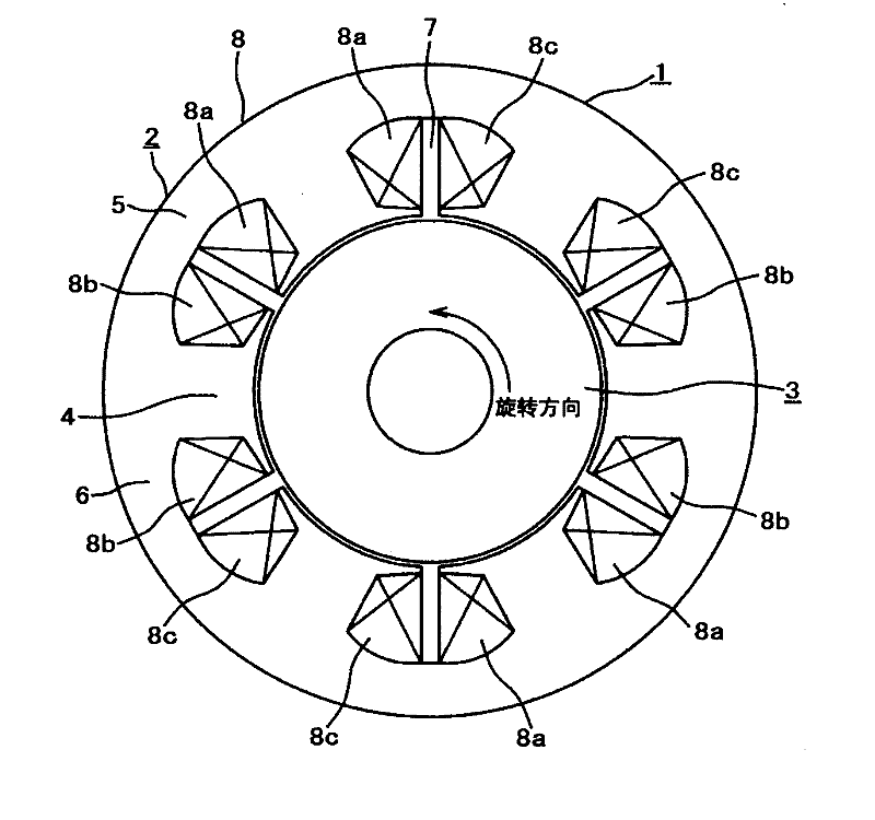
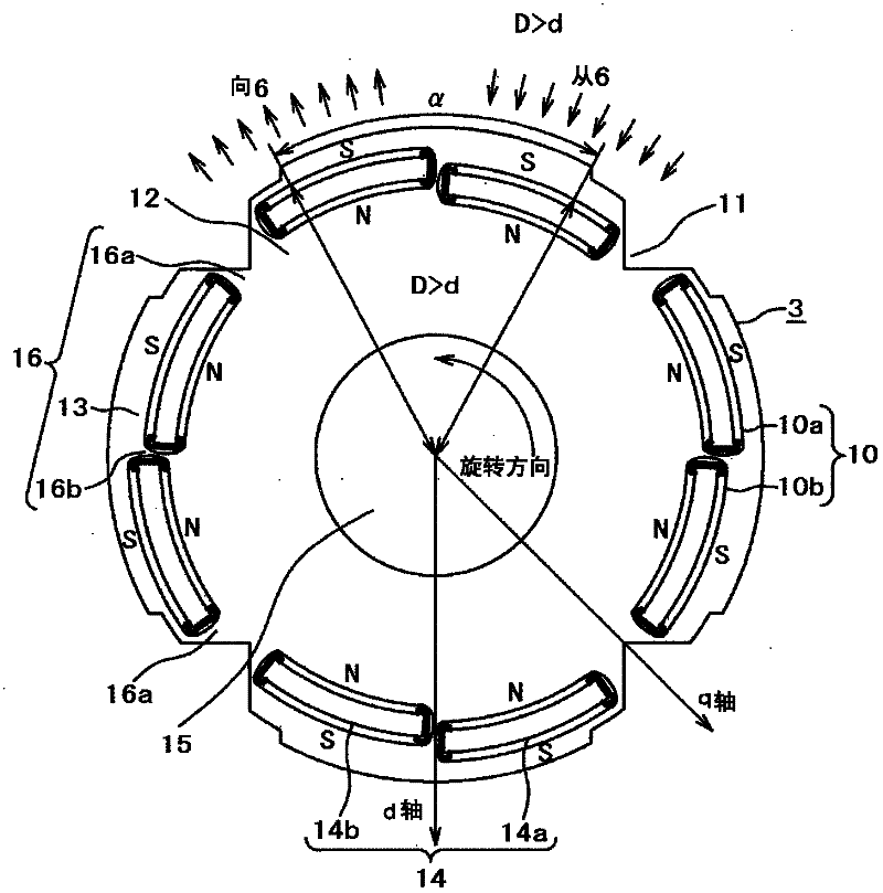
[0059] First, in order to explain the principle of operation of the present invention, a permanent magnet rotating electrical machine according to a first embodiment (Embodiment 1) of the present invention will be described. It should be noted that the attached figure 1 is a cross-sectional view of the permanent magnet rotating electrical machine of Embodiment 1, figure 2 This is a cross-sectional view of, in particular, the rotor in the permanent magnet rotating electrical machine of the first embodiment.

[0060] in the figure 1 Among them, a permanent magnet rotating electrical machine 1 includes a cylindrical stator 2 and a rotor 3 rotatably mounted inside the cylindrical stator. The stator 2 includes: a stator core 6 composed of a plurality of teeth 4 and a core support 5; and an armature winding 8 ( U-phase winding 8a, V-phase winding 8b, and W-phase winding 8c) of the three-phase windings. Here, since the permanent magnet rotating electrical machine 1 has four po...

Embodiment 2

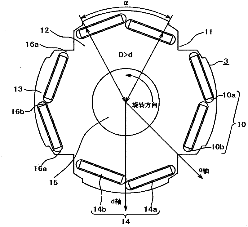
[0072] image 3 is a cross-sectional view showing details of a rotor of a permanent magnet rotating electric machine according to Embodiment 2 of the present invention, wherein figure 2 The same constituent elements are labeled with the same symbol to avoid repeated descriptions.

[0073] Should image 3 The rotor of the permanent magnet rotating electrical machine shown is the same as the above figure 2 The difference is that, instead of the above-mentioned curved (arc-shaped cross-sectional shape) permanent magnets 14a, 14b, flat-shaped permanent magnets with a rectangular cross-section are used, and accordingly, the cross-sections of the insertion holes 10a, 10b are also formed in a rectangular shape. . It should be noted that the above-mentioned two pieces of permanent magnets 14a, 14b are arranged in a so-called inverted "V" shape in such a manner that their opposing parts protrude relative to the outer peripheral surface of the rotor 3, and are arranged in a directi...

Embodiment 3

[0076] Next, attach Figure 4 It is a cross-sectional view showing the details of the rotor of the permanent magnet rotating electric machine according to the third embodiment of the present invention, and here, the above-mentioned figure 2 The same constituent elements are labeled with the same symbol to avoid repeated descriptions.

[0077] in the Figure 4 In the rotor of the permanent magnet rotating electrical machine shown, the difference from the above-mentioned embodiment is that, as can be clearly seen from the figure, the above-mentioned permanent magnets divided into two are permanent magnets 14a and 14b with a rectangular cross section, and the permanent magnets are The magnet insertion holes 10a, 10b are not along the outer peripheral surface of the pole core 13, but are arranged linearly and obliquely to a perpendicular line to the center line of each pole (the line passing through the center of the opening α of the pole core 13). into a straight line. In add...


PUM


Abstract

The present invention provides a permanent magnet rotating motor and a compressor using the same, wherein the permanet magnet rotating motor exerts high efficiency and high performance in a wide range from low speed to high speed. The rotor of the permanent rotating motor is provided with the following components: a rotor core, a plurality of insertion holes which are formed on the rotor core, and a plurality of blocks of permanent magnet, which are inserted into the insertion holes. Furthermore, the insertion holes which are provided with the inserted permanent magnet are arranged that at least two insertion holes are provided on each pole of the rotor. Furthermore the blocks of permanent magnet, which are inserted into the insertion holes, are respectively configured to asymmetric relative to the magnetic pole center of the rotor. Therefore, the following functions are achieved: reducing effect of the demagnetize field caused by armature flux, increasing torque when same electric current is applied, reducing eddy current loss of the permanent magnet, and weakening excitation operation through small electric current. Therefore the permanent magnet rotating motor which is suitable for high-efficiency and high-speed rotation is provided.

Description

technical field [0001] The present invention relates to a permanent magnet rotating electrical machine having a permanent magnet for excitation on a rotor, and more particularly to a permanent magnet rotating electrical machine suitable for use in compressors such as air conditioners, refrigerators, and refrigerators, and a permanent magnet rotating electrical machine using the permanent magnet rotating electrical machine. Motor compressor. Background technique [0002] In an embedded magnet type rotor in which permanent magnets are embedded in the rotor core, when the permanent magnets are arranged on the outer diameter side, the generated torque increases, but on the other hand, demagnetization of the permanent magnets may become a problem. This is because in a permanent magnet rotating electrical machine, torque is generated between the magnetic field generated by the permanent magnet of the rotor and the rotating magnetic field formed by the stator due to attractive and ...

Claims


Application Information

Patent Timeline
IPC IPC(8): H02K21/14H02K1/14H02K1/27
Inventor 涌井真一高畑良一野间启二妹尾正治
Owner HITACHI LTD
Why Eureka
Try Eureka