Fuel cell assembly and vehicle

A technology of fuel cell and fuel cell unit, which is applied in the field of vehicles and can solve problems such as deterioration of fuel utilization rate, increased component weight, and fuel gas leakage

Active Publication Date: 2012-05-09
TOYOTA JIDOSHA KK
View PDF12 Cites 32 Cited by
  • Summary
  • Abstract
  • Description
  • Claims
  • Application Information

AI Technical Summary

Problems solved by technology

Conversely, in order to improve the impact resistance, it is only necessary to increase the rigidity of the reinforcement member, which has to increase the weight of the member, so the deterioration of the fuel efficiency accompanying the increase of the vehicle weight cannot be avoided.
The DC-DC converters described in Patent Document 5 and Patent Document 6 are peripheral devices installed close to the fuel cell. Therefore, if the installation structure is not perfect, the impact of the vehicle collision may penetrate into the fuel cell and cause fuel gas leakage. leakage

Method used


Image

  • Fuel cell assembly and vehicle
  • Fuel cell assembly and vehicle
  • Fuel cell assembly and vehicle

Examples


Embodiment approach 1

[0059] Embodiment 1 of the present invention relates to a fuel cell module in which fuel cell units individually housing a fuel cell stack are provided in a protective structure. In Embodiment 1, a fuel cell system including a fuel cell module is mounted on a vehicle (fuel cell vehicle). Hereinafter, first, the structure of the fuel cell system will be described, and then details of the fuel cell module will be described.

[0060] (system structure)

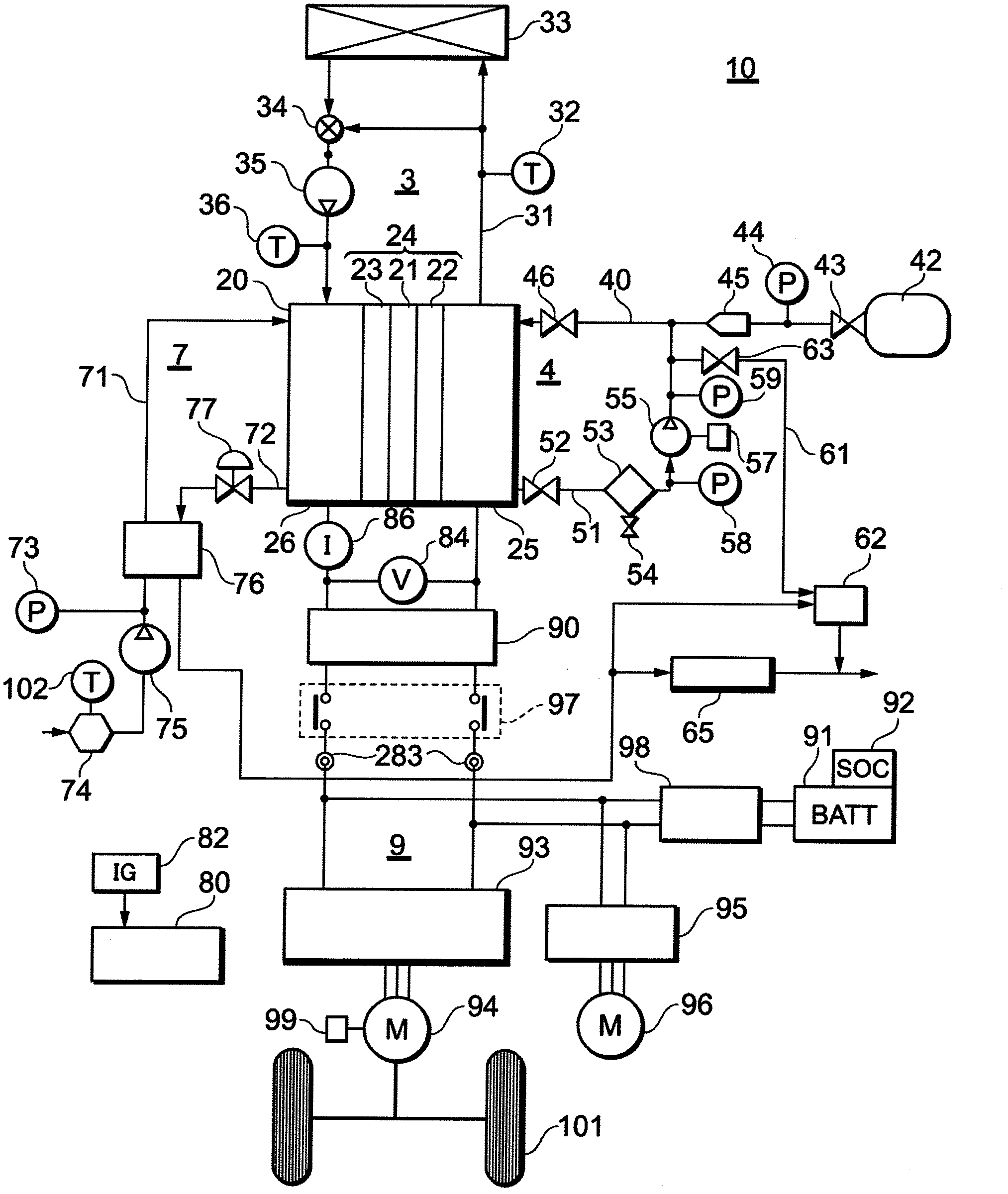
[0061] figure 1 It is a structural diagram of a fuel cell system to which the present invention is applied.

[0062] figure 1 The fuel cell system 10 includes a fuel gas supply system 4 , an oxidizing gas supply system 7 , a coolant supply system 3 , and an electric power system 9 . The fuel gas supply system 4 is a system for supplying fuel gas (hydrogen gas) to the fuel cell 20 . The oxidizing gas supply system 7 is a system for supplying oxidizing gas (air) to the fuel cell 20 . The coolant supply system 3 is a system fo...

Embodiment approach 2

[0155] Embodiment 2 of the present invention relates to a modified example of the fuel cell module.

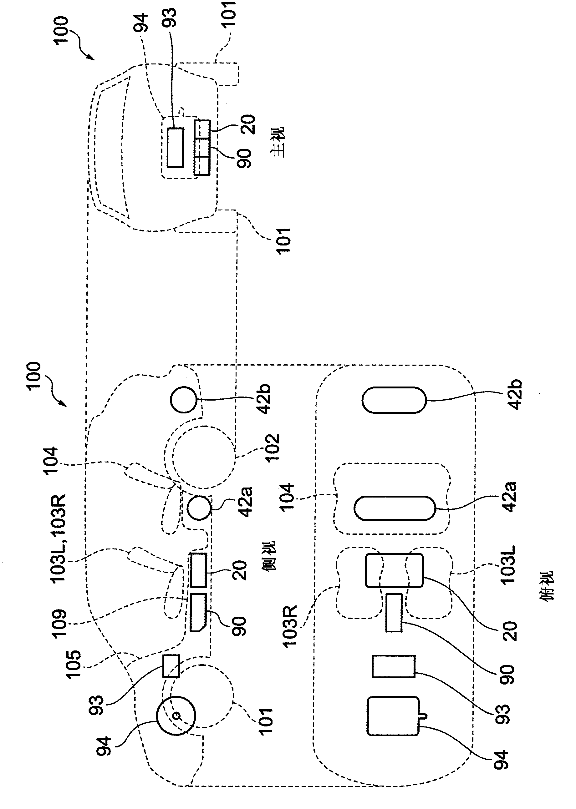
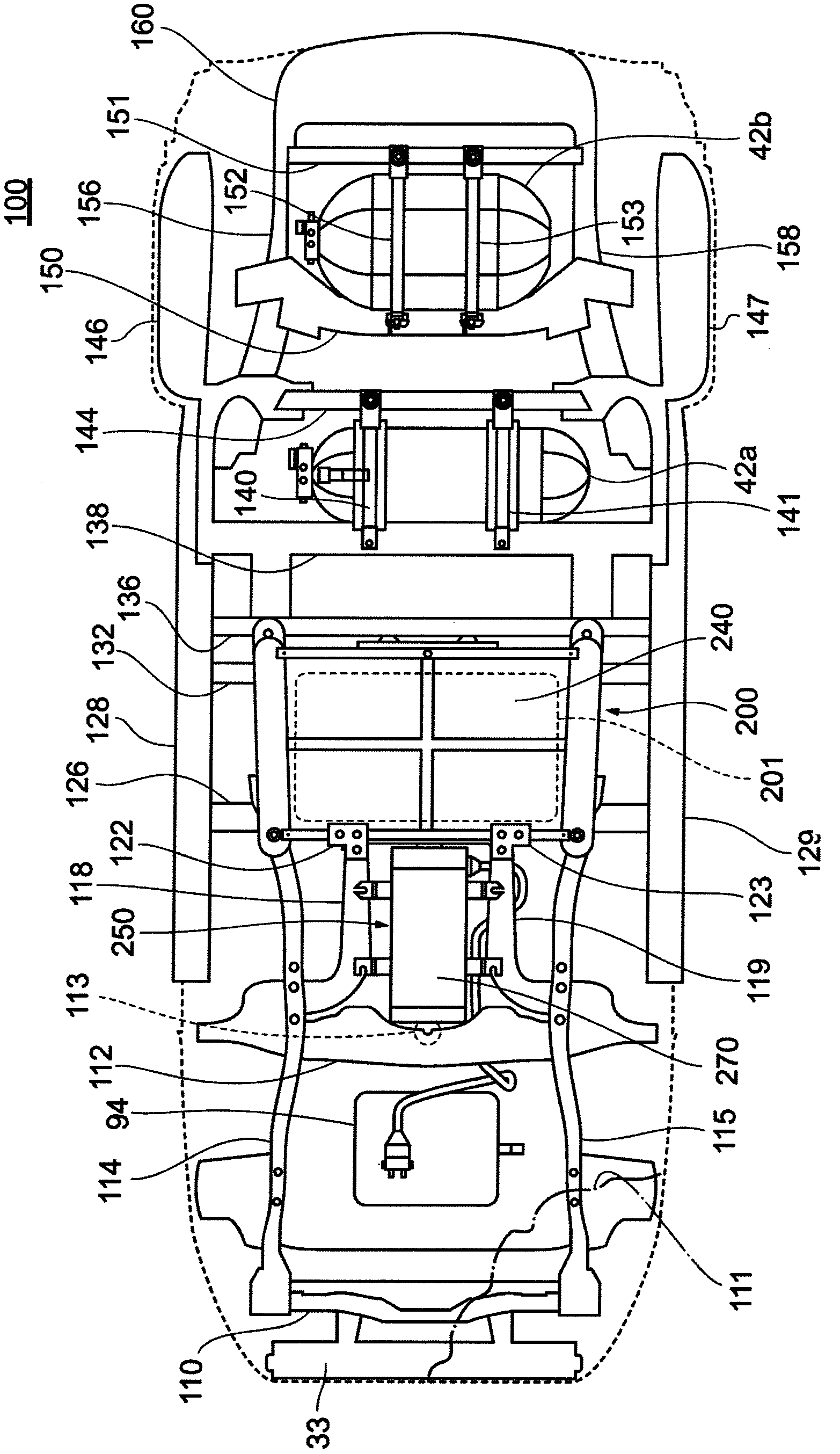
[0156] Figure 11 A perspective view showing the fuel cell module 300 in the second embodiment. Figure 12 A vehicle side view illustrating the arrangement of the fuel cell assembly 300 in Embodiment 2 is shown. Figure 13 A bottom view of a vehicle showing the arrangement of the fuel cell assembly 300 in the second embodiment.

[0157] like Figure 11 and Figure 13 As shown, the fuel cell assembly 300 of the second embodiment is configured by arranging a plurality of fuel cell-related devices, here, the fuel cell unit 201 and the FC converter 90 along the width direction of the vehicle. However, the fuel cell-related devices are not limited to this combination, and other devices related to an inverter may be provided together with the fuel cell unit 201 . The protective structure 310 is formed in a size and shape capable of housing the fuel cell unit 201 and the FC conv...


PUM


Abstract

Provided is a mounting structure for a fuel cell system capable of enduring a collision from the side face of a fuel cell vehicle. The fuel cell system comprises a fuel cell unit (200) for housing a fuel cell, and a protecting structure (220) having a mounting face for mounting the fuel cell unit (200). The protecting structure (220) includes sloped frames (234 and 235) sloped with respect to that mounting face, at positions facing at least one side of the fuel cell unit (200). The protecting structure (220) has the sloped frames (234 and 235) as the structures for bearing the collision impact from the sides. As a result, the protection of the entire height of the fuel cell unit (200) is realized by the lightest structure.

Description

technical field [0001] The present invention relates to a vehicle equipped with a fuel cell system, and particularly relates to a mounting structure of a fuel cell-related device such as a fuel cell or a DC / DC converter. Background technique [0002] A vehicle (hereinafter referred to as a "fuel cell vehicle") that travels by supplying electric power from a fuel cell system and driving a motor for driving the vehicle has been developed. In a fuel cell vehicle, the structural members of the fuel cell system are placed under the floor in the center of the vehicle to ensure safety in the event of a collision. [0003] For example, Japanese Patent Application Laid-Open No. 2005-205945 discloses a vehicle-mounted structure in which a fuel cell unit and an auxiliary unit are arranged adjacent to each other on the floor frame of the fuel cell vehicle along the front-rear direction of the vehicle and along the width of the vehicle. Orientation set the lower part of the body floor s...

Claims


Application Information

Patent Timeline
Patent Type & Authority Applications(China)
IPC IPC(8): B60K1/04H01M8/24B60K8/00B60L11/18B62D25/20H01M8/00H01M8/04
CPCH01M2250/20B60K2001/0438Y02T10/7241B60L11/1896Y02E60/50B60L2240/421B60L2240/36B60L11/1887B62D25/20Y02T10/7216B60L2210/10Y02T10/705Y02T90/34Y02T90/32B60L1/003B60L2210/40B60L11/1803B60L11/1877H01M8/247H01M8/2475B60L11/1898B60K1/04B60L7/16B60L3/0053B60L11/1892Y02T10/642B60L50/51B60L50/66B60L50/72B60L58/40B60L58/33B60L50/71Y02T10/64Y02T10/72Y02T10/70Y02T90/40
Inventor 大桥康彦
Owner TOYOTA JIDOSHA KK
Why Eureka
Try Eureka