Eureka AIR delivers breakthrough ideas for toughest innovation challenges, trusted by R&D personnel around the world.

Mechanism for intelligently controlling moving head of multi-station material forming machine to rotate

A technology of intelligent control and moving head, which is applied in the direction of metal processing, etc., can solve the problems of slow speed, non-rotating moving head of four-column cutting machine, high labor intensity and safety performance, etc., and achieve high punching efficiency, easy and convenient knife die movement, The effect of improving work efficiency and blanking quality

Inactive Publication Date: 2012-05-16
YANCHENG XIONGYING PRECISION MACHINERY
View PDF7 Cites 6 Cited by
  • Summary
  • Abstract
  • Description
  • Claims
  • Application Information

AI Technical Summary

Problems solved by technology

[0003] The purpose of the present invention is to provide an intelligent control multi-station material forming machine moving head rotation mechanism, which overcomes the shortcomings of the old four-column cutting machine that the moving head cannot rotate, slow speed, high labor intensity and safety performance. The mechanism automatically rotates and shifts, and the photoelectric Protection, accurate punching positioning, high degree of automation, fast speed, improved work efficiency, saving raw materials, good safety performance, and easy operation

Method used


Image

  • Mechanism for intelligently controlling moving head of multi-station material forming machine to rotate
  • Mechanism for intelligently controlling moving head of multi-station material forming machine to rotate

Examples


Embodiment Construction

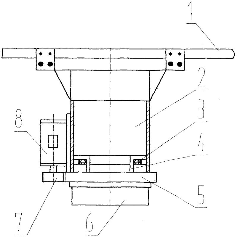
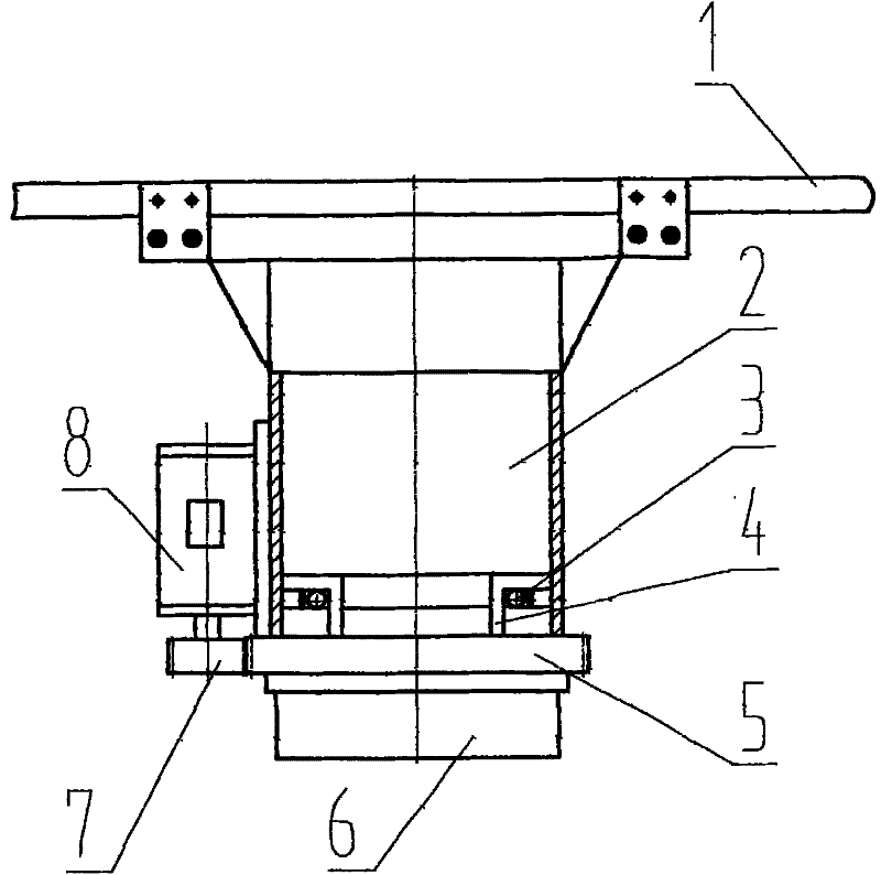
[0009] The present invention is mainly composed of a translation guide rail 1, a moving head body 2, a plane bearing 3, a connecting shaft 4, a main transmission gear 5, a die fixing frame 6, a motor gear 7, and a servo motor 8. The translation guide rail 1 is installed at the lower end of the upper body On both sides, the moving head body 2 is installed at the lower ends of the translation guide rails 1 on both sides. The moving head body 2 is welded by steel plates, and the plane bearing 3 is installed inside, which is connected by the connecting shaft 4. The main transmission gear 5 is fixed at the lower end of the connecting shaft 4. The lower end of the gear 5 is equipped with a die holder 6, the side of the moving head body 2 is equipped with a servo motor 8, and the lower end of the servo motor 8 is equipped with a motor gear 7, which cooperates with the main transmission gear 5, and the motor gear 7 drives the main transmission gear 5 The rotation drives the die holder ...


PUM


Abstract

The invention discloses a mechanism for intelligently controlling a moving head of a multi-station material forming machine to rotate. The mechanism mainly comprises a shifting guide rail, a moving head body, a plane bearing, a connecting shaft, a main drive gear, a cutting die fixing frame, a motor gear and a servo motor, wherein the shifting guide rail is arranged on two sides of the lower end of an upper machine body; the moving head body is arranged at the lower end of the shifting guide rail on the two sides, and is formed by welding a steel plate; the plane bearing is arranged in the moving head body, and is connected with the moving head body through the connecting shaft; the main drive gear is fixed at the lower end of the connecting shaft; the cutting die fixing frame is arranged at the lower end of the main drive gear; the servo motor is arranged on the side face of the moving head body; and the motor gear is arranged at the lower end of the motor, and is matched with the main drive gear, and drags the main drive gear to rotate so as to drive the cutting die fixing frame rotate 360 degrees. The mechanism has a reasonable and compact structure; the servo motor drags the cutting die fixing frame to move so as to drive a cutting die to rotate, so that the blanking efficiency is high, the angle of the cutting die is positioned more accurately, the cutting die moves more easily and conveniently, and the work efficiency and blanking quality are effectively improved.

Description

Technical field [0001] The invention relates to a light industry four-column gantry cutting machine, in particular to an intelligently controlled multi-station material molding machine moving head rotation mechanism. Background technique [0002] At present, well-known, the gantry type hydraulic unloading machine that is used for the cutting operation of non-metal material industry. The translation of the moving head adopts the rotation of the trapezoidal screw to drive the translation of the moving head. It can only move left and right, and cannot rotate. The moving area of ​​the knife mold is too small, the machining error is quite large, and it causes a lot of waste in the process of raw material processing, which directly affects the work efficiency and the quality of the workpiece. Contents of the invention [0003] The purpose of the present invention is to provide an intelligent control multi-station material forming machine moving head rotation mechanism, which ov...

Claims


Application Information

Patent Timeline
Patent Type & Authority Applications(China)
IPC IPC(8): B26D5/08B26F1/38
Inventor 郭乃宏施付堂杜万勇
Owner YANCHENG XIONGYING PRECISION MACHINERY
Why Eureka
Eureka Blog
Learn More