
Winding device
A technology of winding device and wire hole, applied in the directions of transportation and packaging, transportation of filamentous materials, thin material processing, etc., can solve the problems of slow pay-off speed of the spindle, waste of raw materials, disorder of warp threads, etc., and achieve the pay-off speed of the spindle. The effect of stable, simple and stable structure, convenient installation and replacement
- Summary
- Abstract
- Description
- Claims
- Application Information
AI Technical Summary
Problems solved by technology
Method used
Image

Examples
Embodiment Construction
[0022] The preferred embodiments of the present invention will be described in detail below in conjunction with the accompanying drawings, so that the advantages and features of the present invention can be more easily understood by those skilled in the art, so as to define the protection scope of the present invention more clearly.
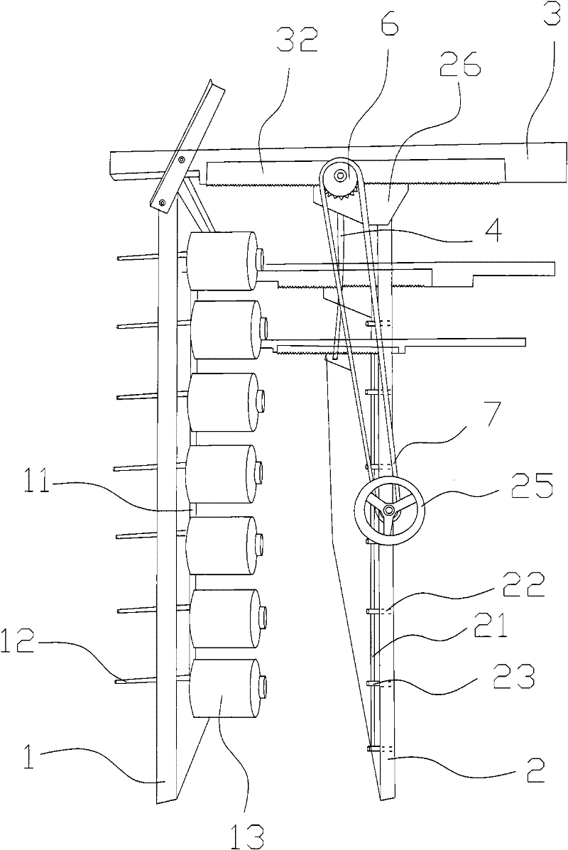
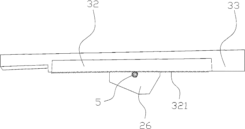
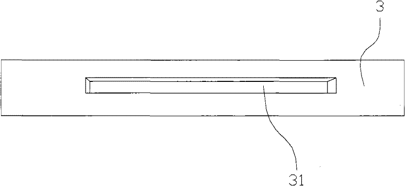
[0023] From attached figure 1 Schematic diagram of the chip collecting part of the winding device, attached figure 2 Schematic diagram of the connection between the beam and the guide rail of the winding device, and the attachment image 3 The structure diagram of the guide rail and the attached Figure 4 It can be seen from the schematic diagram of the structure of the driving gear and the rotating handle that the present invention provides a winding device, which includes a fixed frame 1, a beam 3 with one end fixedly mounted on the top of the fixed frame 1, and a sliding connection with the beam 3. The free frame 2, the fixed frame 1 has a ...
PUM
 Abstract
Description
Claims
Application Information