A pulverized coal burner and boiler

A pulverized coal burner and pulverized coal technology are applied to burners, burners that burn powder fuels, and combustion using multiple fuels, etc., which can solve the problems of powder accumulation and slagging, and solve the problems of powder accumulation and slagging, The effect of reducing wall temperature and preventing slagging

Active Publication Date: 2014-10-22
YANTAI LONGYUAN POWER TECH
View PDF6 Cites 0 Cited by
  • Summary
  • Abstract
  • Description
  • Claims
  • Application Information

AI Technical Summary

Problems solved by technology

[0007] The above-mentioned pulverized coal burner improves the combustion efficiency of pulverized coal and reduces the emission of nitrogen oxides. At the same time, due to the increased residence time of pulverized coal in the burner, there are also problems of easy powder accumulation and slagging.

Method used


Image

  • A pulverized coal burner and boiler
  • A pulverized coal burner and boiler
  • A pulverized coal burner and boiler

Examples


Embodiment 1

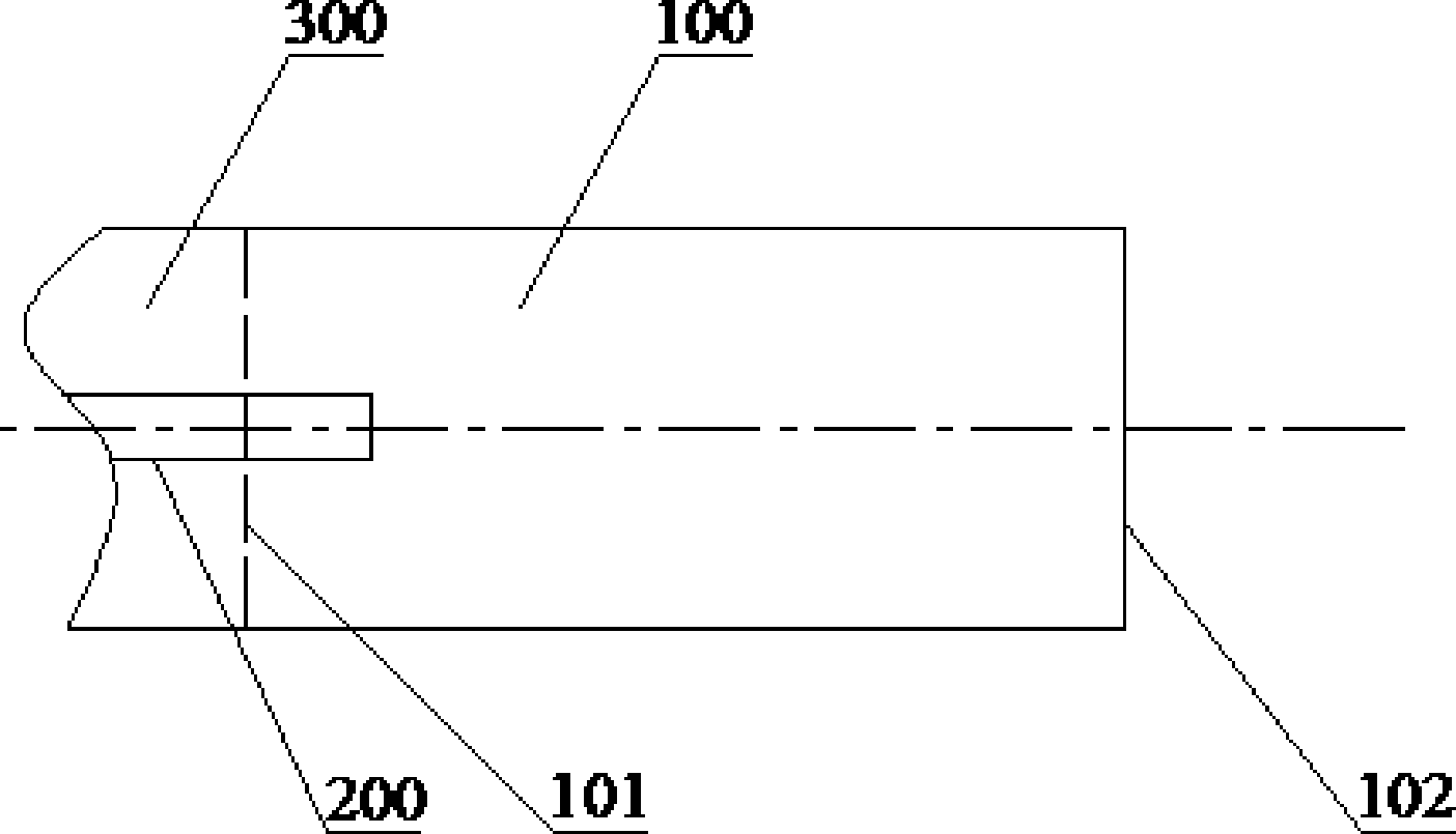
[0037] Please refer to figure 2 , which is a longitudinal structural view of the pulverized coal burner provided in Embodiment 1 of the present invention.

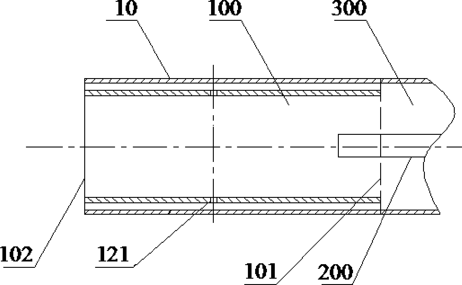
[0038] For the convenience of description, figure 2 The air inlet pipe 300 is also shown in the figure; the fire source 200 extends into the internal combustion chamber 100 from the air inlet pipe 300 , and the air inlet pipe 300 communicates with the inlet 101 . The heat source is a continuous heat source to continuously ignite the pulverized coal.

[0039] The pulverized coal burner provided in Embodiment 1 of the present invention is a double-layer sleeve structure of the outer cylinder 10 and the inner cylinder 100, and the pulverized coal burner includes a heat source 200 and an internal combustion chamber. The inner tube 100 serves as the internal combustion chamber.

[0040] The heat source 200 is located in the internal combustion chamber, and the internal combustion chamber has an inlet and an outlet; the hea...

Embodiment 3

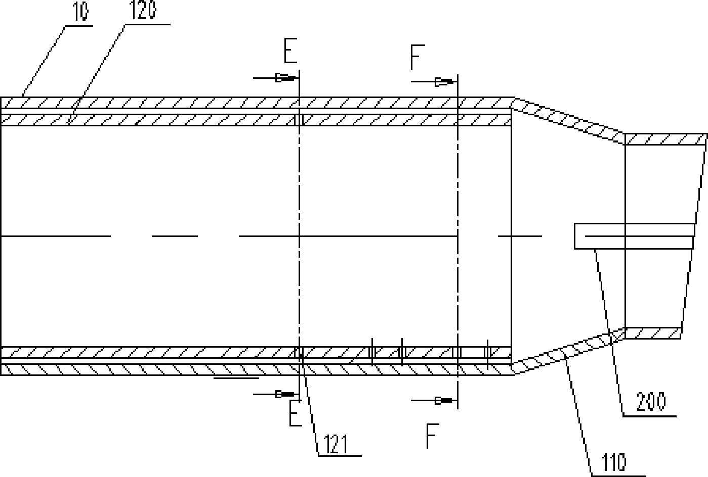
[0056] see Figure 6 to Figure 9 , Figure 6 The sectional structure diagram of the pulverized coal burner provided for the second embodiment of the present invention; Figure 7 for Figure 6 The B-B direction sectional view shown; Figure 8 for Figure 6 The C-C sectional view shown; Figure 9 for Figure 6 The D-D direction sectional view is shown.

[0057] When the pulverized coal airflow ignited in the internal combustion chamber 100 is drawn out through the outlet and introduced into the boiler furnace, in order to make the drawn high-temperature pulverized coal combustion flame have higher rigidity and adapt to the overall combustion organization needs of the boiler furnace, internal combustion can also be used. The chamber 100 is provided with an accelerated exit section. Such as Figure 6 As shown, the pulverized coal burner also has an acceleration outlet section 130 connected to the rear end of the combustion chamber 120 .

[0058] The through hole 121 may o...


PUM


Abstract

The invention discloses a coal burner which is in a double-layer sleeve structure with an outside cylinder and an inside cylinder. The coal burner comprises a heat source and an internal combustion chamber, and the inside cylinder is utilized as the internal combustion chamber; the heat source is positioned in the internal combustion chamber, and the internal combustion chamber is provided with an inlet and an outlet; the heat source can be used for igniting coal dust airflow which passes through the internal combustion chamber, so that coal dust is subjected to imperfect combustion in the internal combustion chamber; and a cavity arranged between the outside cylinder and the inside cylinder is connected with an air source, the pressure of the air source is greater than that of the coal dust airflow, and the cylinder wall of the inside cylinder is provided with a through hole. The coal burner provided by the invention can be used for solving the technical problems such as coal depositing, scorification and the like on the premise of ensuring the combustion efficiency of the coal dust.

Description

technical field [0001] The invention relates to a pulverized coal combustion equipment, in particular to a pulverized coal burner, and also to a pulverized coal boiler. Background technique [0002] The applicant's first application number is 200910175071.4, and the patent application titled "a pulverized coal burner and a boiler with the pulverized coal burner" provides a pulverized coal burner, please refer to figure 1 , This figure schematically shows the structure of the pulverized coal burner provided by the above-mentioned invention. The pulverized coal burner includes a heat source 200 and an internal combustion chamber 100. The internal combustion chamber 100 has an inlet 101 and an outlet 102. The internal combustion chamber 100 forms a suitable space and creates favorable conditions for the ignition and combustion of pulverized coal. The inlet 101 of the internal combustion chamber 100 communicates with the primary air pulverized coal pipeline, and the pulverized ...

Claims


Application Information

Patent Timeline
Patent Type & Authority Patents(China)
IPC IPC(8): F23D1/00F23C5/08
Inventor 王雨蓬唐宏苗雨旺王雨勃程昌业龚泽儒张超群崔星源刘鹏雷刚
Owner YANTAI LONGYUAN POWER TECH
Why Eureka
Try Eureka