Imaging system using plane mirror to integrate lights and optical measuring device

A flat mirror and imaging system technology, applied in the field of optical measurement, can solve problems such as high cost, chromatic aberration, and difficulty in realizing efficient illumination of detection spots, and achieve the effect of low cost and simple structure

Inactive Publication Date: 2013-05-22
INST OF MICROELECTRONICS CHINESE ACAD OF SCI +1
View PDF6 Cites 0 Cited by
  • Summary
  • Abstract
  • Description
  • Claims
  • Application Information

AI Technical Summary

Problems solved by technology

The disadvantages of this structure are: 1) The two surfaces of the sheet can form a ghost image, which affects the imaging quality, position calibration and measurement
2) Regardless of transmission or reflection, after the light beam passes through the spectroscopic sheet, the polarization state changes; if the polarization control of the detection beam is to be realized, a polarizer needs to be installed between the beam splitter and the sample; such imaging is affected by the polarization characteristics of the sample and the polarization of the detection beam. State restrictions
3) In the case of broad-band beam transmission, when the beam is a parallel beam, chromatic aberration will occur; when the beam is converging or diverging, the beam imaging will be separated along a single direction, which can seriously affect the measurement and imaging of samples with uneven surface structures ; This problem can be corrected by setting the same spectroscopic sheet to correct the chromatic aberration and the aberration caused by different incident angles, but it increases the complexity of the system
If this method is applied to the synthetic light imaging system, the disadvantages of this method are 1) the processing of the hollow reflector is difficult and the cost is high; 2) due to its centrosymmetric structure, the reflected beam of the probe beam passing through the sample surface will completely pass through The hollow structure returns, theoretically, the imaging of the detection spot cannot be realized in the image detector; 3) It is not easy to realize the efficient illumination of the surrounding part of the detection spot

Method used


Image

  • Imaging system using plane mirror to integrate lights and optical measuring device
  • Imaging system using plane mirror to integrate lights and optical measuring device
  • Imaging system using plane mirror to integrate lights and optical measuring device

Examples


Embodiment 1

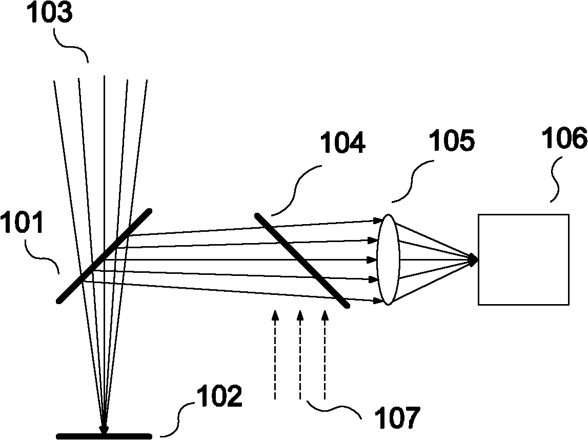
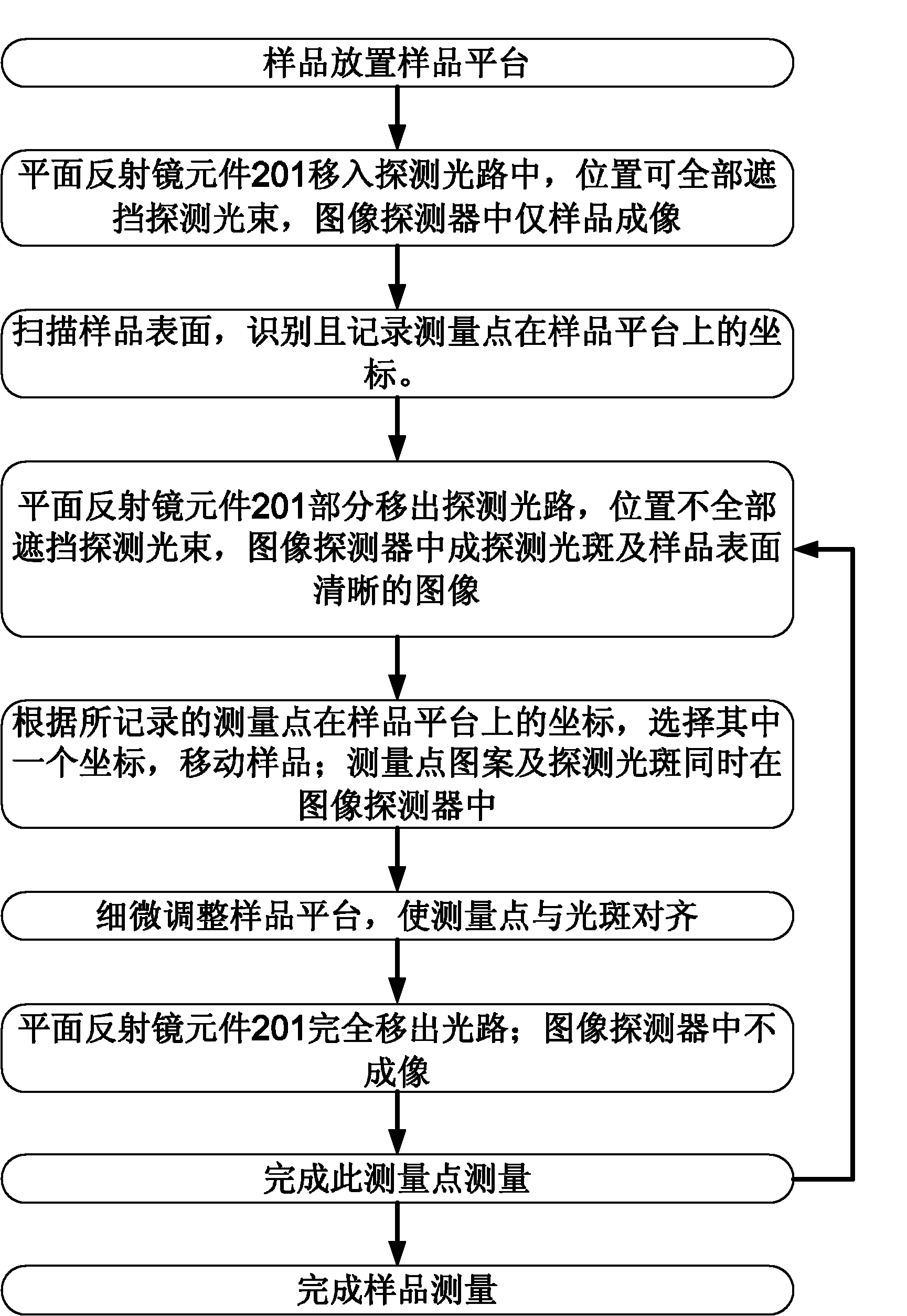
[0044] Such as Figure 3b As shown, the imaging system of this embodiment includes: a first movable mirror 201 , a sample 202 , a detection beam 203 , a beam splitter 204 , an imaging focusing unit 205 , an image detector 206 and an illumination beam 207 . The flowchart of this embodiment consists of Figure 3a Shown, the specific technical scheme of its key steps is as follows:

[0045] When measuring point identification and positioning, such as Figure 3b As shown, the first movable reflector 201 moves into the detection beam 203, and the detection beam 203 is completely incident on the non-reflective surface of the first movable reflector 201 and is completely blocked; after the illumination beam 207 is reflected by the beam splitter 204, it is incident on the The reflective surface of the first movable mirror 201 is reflected by the first movable mirror 201 and illuminates the surface of the sample 202 (the optical path is not shown). The reflected light beam 207 on th...

Embodiment 2

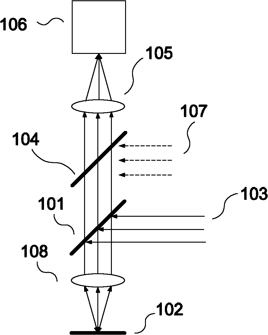
[0053] Such as Figure 4b As shown, the imaging system of this embodiment includes: a second movable mirror 201 ′, a first movable mirror 201 ″, a sample 202 , a detection beam 203 , an imaging focusing unit 205 , an image detector 206 and an illumination beam 207 . The flowchart of this embodiment consists of Figure 4a Shown, the specific technical scheme of its key steps is as follows:

[0054] When measuring point identification and positioning, such as Figure 4b As shown, the second movable mirror 201' moves into the optical path of the reflected beam of the probe beam 203 on the surface of the sample 202. The first movable mirror 201" moves into the detection beam 203 (the dotted line position), and the detection beam 203 is completely incident on the non-reflective surface of the first movable mirror 201", and is completely blocked. The illuminating beam 207 is reflected by the first movable mirror 201 ″, and irradiates the surface of the sample 202; the reflected l...


PUM

PropertyMeasurementUnit
thicknessaaaaaaaaaa
thicknessaaaaaaaaaa

Abstract

The invention belongs to the technical filed of optical measurement, and more particularly relates to an imaging system using a plane mirror to integrate lights and an optical measuring device. The imaging system comprises an imaging light-gathering unit, an image detector and a first removable reflecting mirror, wherein a first light beam is emitted to a sample, and a second light beam is transmitted to the sample through the first removable reflecting mirror, the light reflected from the surface of the sample is imaged on the image detector by the imaging light-gathering unit, the first removable reflecting mirror is positioned in or out of a system light path so that the first light beam and the second light beam are superposed or separated, and through adjusting the removable reflecting mirror, identification and positioning of measuring points and position calibration and measurement of sample surface measuring points and detection light beam light spots can be realized. According to the invention, self characteristics such as luminous flux, chromatism, aberration, polarization and the like of a detection light path are completely not affected, thus imaging without double images can be realized; and in addition, the structure is simple and the cost is low.

Description

technical field [0001] The invention relates to the technical field of optical measurement, and in particular to an imaging system and an optical measurement device that combine light using a plane mirror. Background technique [0002] In the optical measurement system, it is usually necessary to observe the surface structure of the target sample and the shape and position of the probe beam on the sample surface; imaging system. To realize the measurement of the specified position on the sample surface, the imaging system is required to be able to simultaneously observe the sample surface structure and the position of the probe beam spot on the sample surface, so as to realize the calibration of the probe beam and the specified measurement position. In addition, the imaging system with integrated image recognition function can realize the automatic recognition and calibration of the same repeated structure on the sample surface, so as to realize the automation of measuremen...

Claims


Application Information

Patent Timeline
Patent Type & Authority Patents(China)
IPC IPC(8): G02B27/14G01B11/00G01B11/24G01N21/84
Inventor 刘涛李国光艾迪格·基尼欧马铁中夏洋严晓浪
Owner INST OF MICROELECTRONICS CHINESE ACAD OF SCI
Why Eureka
Try Eureka