Control system and method for camera device

A device control and camera technology, which is applied to the components of the TV system, image data processing, TV, etc., can solve the problem that the shooting position and lens angle of the camera device cannot be adjusted manually, and achieve the effect of improving efficiency and accuracy

Inactive Publication Date: 2012-05-16
WARECONN TECH SERVICE (TIANJIN) CO LTD
View PDF4 Cites 3 Cited by
  • Summary
  • Abstract
  • Description
  • Claims
  • Application Information

AI Technical Summary

Problems solved by technology

However, if the monitoring personnel are disabled persons with limited mobility or general paralysis, they wi

Method used


Image

  • Control system and method for camera device
  • Control system and method for camera device
  • Control system and method for camera device

Examples


Embodiment Construction

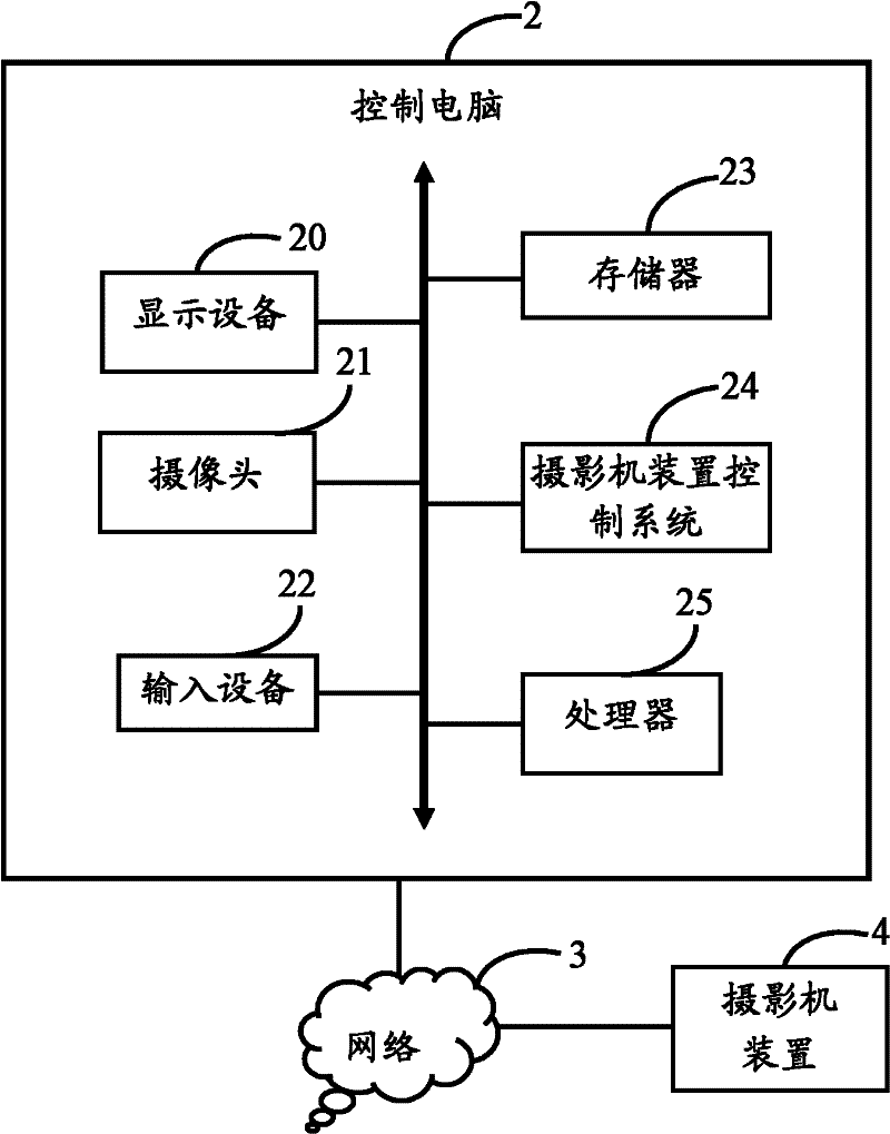
[0024] Such as figure 1 As shown, it is a schematic diagram of the application environment of the preferred embodiment of the camera device control system of the present invention. In this embodiment, the camera device control system 24 runs in the control computer 2 . The control computer 2 also includes a display device 20 , a camera 21 , an input device 22 , a memory 23 and a processor 25 connected via a data bus.

[0025] In this embodiment, the control computer 2 is connected to the camera device 4 through the network 3 . Wherein, the network 3 may be an intranet or an Ethernet, or may be the Internet or other types of communication networks.

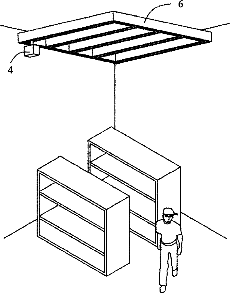
[0026] refer to figure 2 As shown, the camera device 4 is installed in a rail system 6 . In this embodiment, the types of the track system 6 include, but are not limited to, actuation methods such as crawler belt drive type, electric pulley type, and camera built-in motor type. The track system 6 can be set on the ceiling of ...


PUM


Abstract

The invention relates to a control system and method for a camera device. The method comprises the following steps: controlling a computer to obtain an image shot by a camera; utilizing an eyeball detecting technique to detect an eyeball area in the obtained image, comparing the detected eyeball area with a preset eyeball sample according to the height of the detected eyeball area and a coordinate value of an eyeball position, and obtaining a matched eyeball sample; and obtaining a preset control instruction corresponding to the matched eyeball sample and sending the control instruction to the camera device, thereby adjusting a shooting position of the camera device, a lens angle and a focal length. The control system can be utilized to automatically control the camera device to move on a track system according to the eyeball state and position change of a monitor.

Description

technical field [0001] The invention relates to a camera device control system and method. Background technique [0002] When the traditional camera device uses the track system for security monitoring, the monitoring personnel need to pay attention to the picture of the monitoring scene at any time. When unknown objects (including people) appear in the picture, the monitoring personnel can only rely on the dedicated controller of the camera device, manually Adjust the position of the camera device on the rail system, as well as the angle and focal length of the lens of the camera device to obtain a clearer object image. However, if the monitoring personnel are disabled persons with limited mobility or general paralysis, they will not be able to manually adjust parameters such as the shooting position and lens angle of the camera device. Contents of the invention [0003] In view of the above, it is necessary to provide a camera device control system and method, which can...

Claims


Application Information

Patent Timeline
IPC IPC(8): H04N5/232G06T7/20
Inventor 李后贤李章荣罗治平
Owner WARECONN TECH SERVICE (TIANJIN) CO LTD
Why Eureka
Try Eureka