High lift system for an airplane, airplane system and propeller airplane having a high lift system

A technology of aircraft and propeller, which is applied in the field of propeller aircraft, can solve problems such as increased weight, and achieve the effect of reducing operating costs and reducing development risks

Inactive Publication Date: 2012-05-16
AIRBUS OPERATIONS GMBH
View PDF6 Cites 6 Cited by
  • Summary
  • Abstract
  • Description
  • Claims
  • Application Information

AI Technical Summary

Problems solved by technology

[0006] The known prior art design approach to avoid constraining the aircraft too much with respect to tail stall consists in providing a suitable increase in the surface area of ​​the elevator unit or an increase in the lever arm of the tail unit, and thereby increasing the weight

Method used


Image

  • High lift system for an airplane, airplane system and propeller airplane having a high lift system
  • High lift system for an airplane, airplane system and propeller airplane having a high lift system
  • High lift system for an airplane, airplane system and propeller airplane having a high lift system

Examples


Embodiment Construction

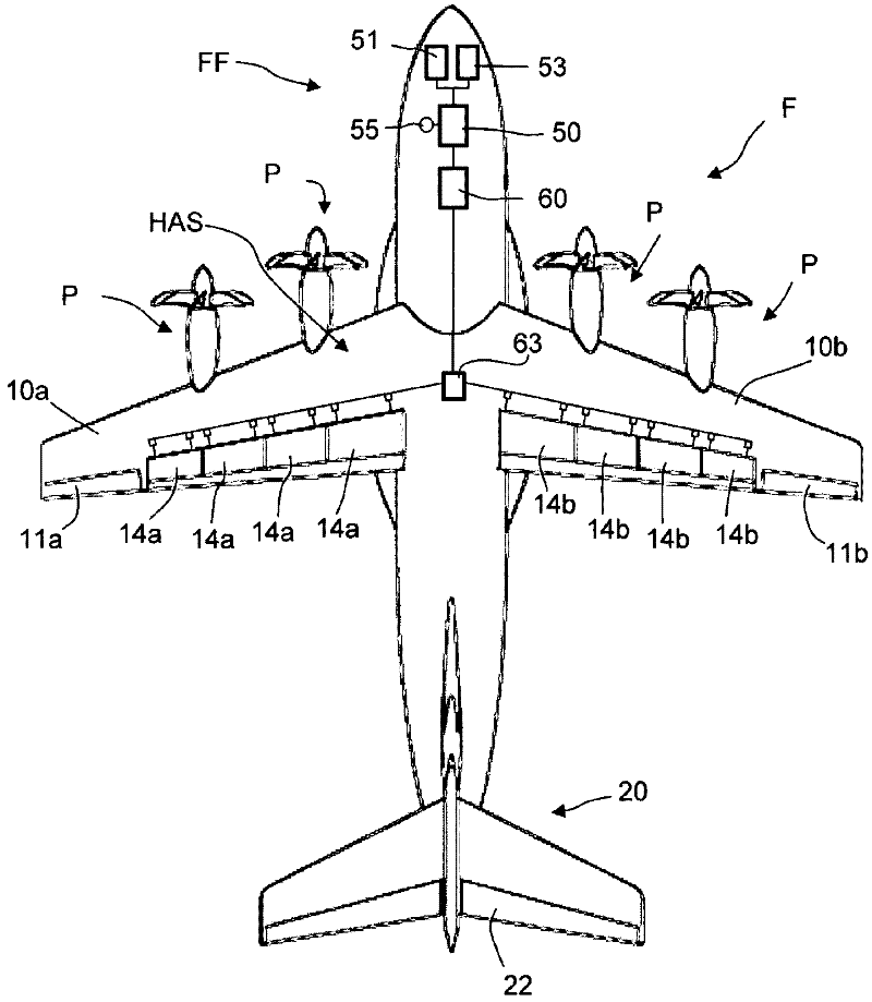
[0045] figure 1 An example of an embodiment of an aircraft F featuring closed-loop control with two wings 10a, 10b is shown. The wings 10a, 10b each have at least one aileron 11a or 11b, respectively, and at least one trailing edge flap 14a, 14b. The wings 10a, 10b can each optionally have a plurality of spoilers and / or slats. Furthermore, the aircraft F has a vertical empennage unit 20 with at least one rudder and one elevator 22 . The vertical tail unit 20 can be designed, for example, as a T-tail unit or as a cross-tail unit. The aircraft F may in particular be a propeller aircraft with propellers driven by the engines P. In the case of the latter, in particular it can be arranged that in a propeller aircraft, the propeller driven by the engine P is mounted on the wings 10a, 10b, such as figure 1 shown in . In addition, the propeller aircraft F may be a high-wing aircraft.

[0046] The aircraft F or the flight management system FF has a flight control device 50 and an...


PUM


Abstract

The invention relates to a high lift system for an airplane, comprising: one or more high lift flaps (14a, 14b); a control device (60, 160) having a control function for generating position commands for setting the adjustment state of the high lift flaps (14a, 14b); a drive device (63, 163) coupled to the high lift flaps (14a, 14b) and is designed such that it adjusts the high lift flaps (14a, 14b) between a retracted position and an extended position on the basis of control commands, wherein the control function creates position commands based on input values and sends them to the drive device (63, 163) for adjusting the high lift flaps (14a, 14b). The control function comprises a function for automatically retracting the high lift flap (14a, 14b) during flight, which creates a control command in a flight state in which the high lift flap (14a, 14b) is in an extended position, taking into consideration an engine thrust and a minimal flight altitude, after the high lift flap (14a, 14b) is retracted.

Description

technical field [0001] The invention relates to an aircraft lift-increasing system, an aircraft system and a propeller aircraft with an increase-in-lift system. Background technique [0002] With regard to the ability to control the longitudinal movement of the aircraft, there is a risk of flow separation on the elevator unit ("tail stall"). The risk of flow separation over the elevator unit - which has the consequence of a so-called "negative tail stall" - is primarily if a strong downthrust must be generated by the elevator unit in the high-lift configuration (where the landing flaps are extended) occurs under the circumstances. In the case of a turboprop, this effect is enhanced by the effect of the propeller thrust, which is directed via the landing flaps onto the elevator unit. [0003] Usually, this effect is counteracted by an appropriate command of the elevator unit, so that in this way the stability and controllability standards derived from the airworthiness regu...

Claims


Application Information

Patent Timeline
Patent Type & Authority Applications(China)
IPC IPC(8): B64C9/18B64C13/16B64C9/32
CPCB64C13/16B64C9/18
Inventor 伊娜·鲁克斯彼得·谢弗斯迈克尔·威尔默奥拉夫·斯皮勒
Owner AIRBUS OPERATIONS GMBH
Why Eureka
Try Eureka