Lower-thread tension control device for sewing machine, and sewing machine

A technology for tension control and sewing machines, which is applied to the loop mechanism of sewing machines, bobbin winding in sewing machines, and sewing machine components. The effect of easy loading and unloading

Active Publication Date: 2012-05-16
NSD
View PDF7 Cites 15 Cited by
  • Summary
  • Abstract
  • Description
  • Claims
  • Application Information

AI Technical Summary

Problems solved by technology

[0007] However, in the bobbin thread control device for the sewing machine of Patent Document 1, since the bobbin is pressed by the permanent magnet, the end of the bobbin is pressed against the large-diameter portion of the support shaft to generate tension of the bobbin thread, so the tension of the bobbin thread depends on Due to the friction between the bobbin and the support shaft, the thread tension cannot be controlled finely, and it cannot be controlled with high precision.
[0008] Moreover, in the bobbin thread control device of the sewing machine of the above-mentioned patent document 2, the tension of the bobbin thread is controlled by making the magnetic body move forward and backward relative to the bobbin thread guide part by the electromagnet, so the tension of the bobbin thread depends on the frictional force between the bobbin thread and the magnetic body, and cannot be finely adjusted. Control the bobbin thread tension precisely, and cannot control it with high precision

Method used


Image

  • Lower-thread tension control device for sewing machine, and sewing machine
  • Lower-thread tension control device for sewing machine, and sewing machine
  • Lower-thread tension control device for sewing machine, and sewing machine

Examples


Embodiment 1

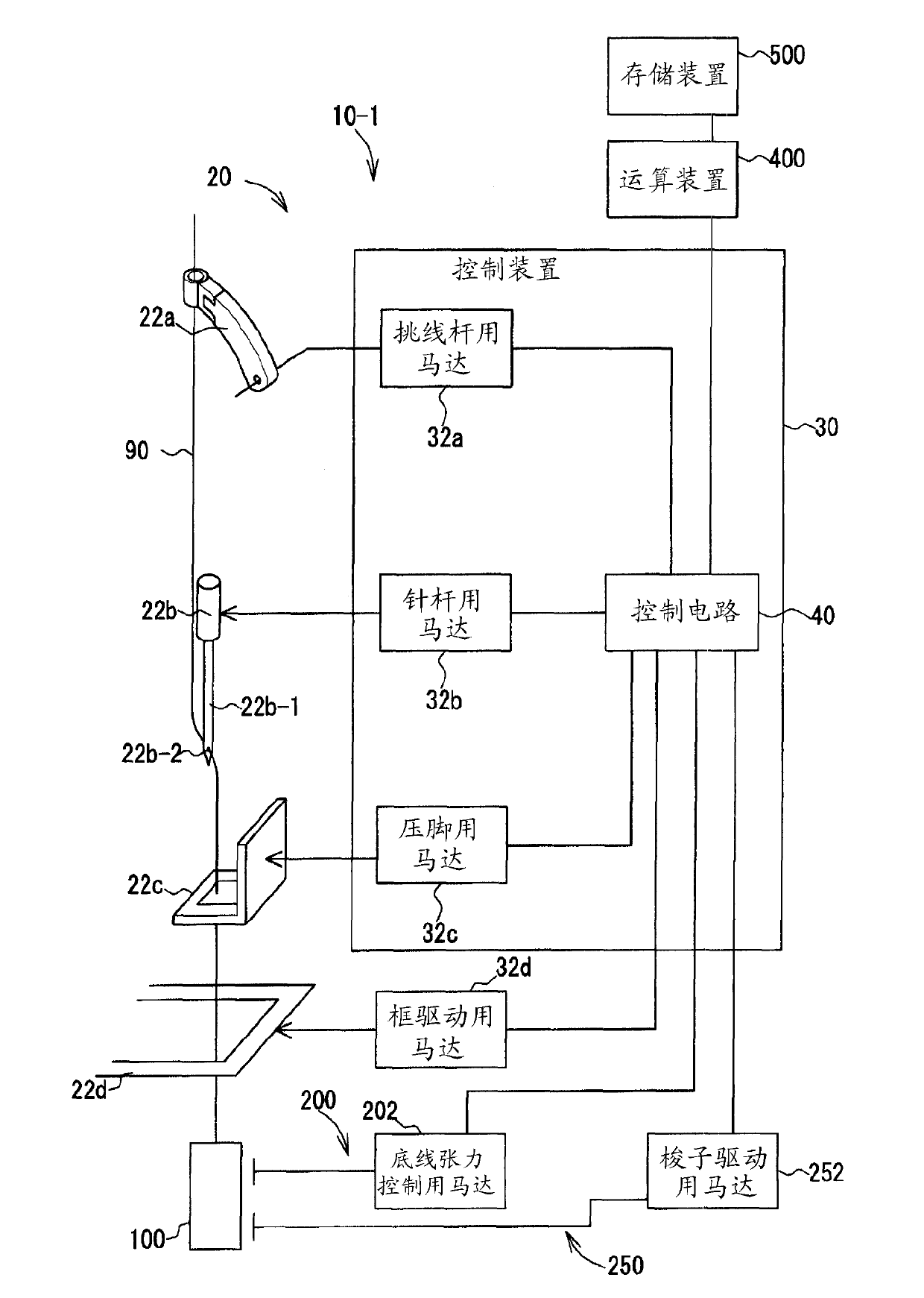
[0080] As an embroidery sewing machine 1 based on the sewing machine of the present invention, such as Figure 1 to Figure 13 As shown in the structure, it has: a sewing machine table 3, embroidery heads 10-1 to 10-n, a sewing frame (which can be used as a holding frame or an embroidery frame) 22d, a frame driving motor 32d, a shuttle 100, and a bobbin thread tension control mechanism 200, a shuttle driving part 250, a bobbin 300, an arithmetic device 400, and a storage device 500.

[0081] Here, the sewing machine table 3 is substantially flat, such as Figure 4 As shown in FIG. 1 , there is a plate-shaped table main body 4 and a needle plate 5 provided in an opening formed in the table main body 4 .

[0082] Furthermore, the embroidery heads 10-1 to 10-n are provided above the sewing machine table 3, and each of the embroidery heads 10-1 to 10-n is arranged in a substantially straight line at predetermined intervals. That is, a frame (not shown) is erected from the upper s...

Embodiment 2

[0159] The embroidery sewing machine in the second embodiment has substantially the same structure as that in the first embodiment, but is different in that the middle shuttle has a full rotation structure. That is, the middle shuttle in the above-mentioned embodiment 1 is a semi-rotary type, while the middle shuttle in the embodiment 2 is a full-rotation type. Compared with the embodiment 1, the structure of the bobbin thread tension control mechanism part and the shuttle driving part is different.

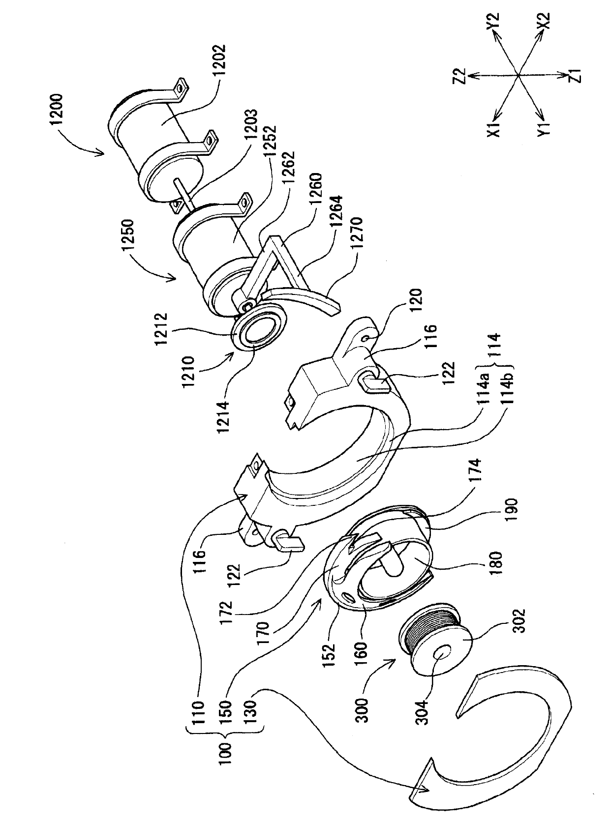
[0160] The structure of the shuttle 100 in the present embodiment, the bobbin thread tension control mechanism part 1200, and the shuttle driving part 1250 is as follows: Figure 17 As shown, the structure of the shuttle 100 is the same as that of the shuttle 100 in the first embodiment.

[0161] The bobbin thread tension control mechanism unit 1200 includes a bobbin thread tension control motor 1202 and a rotary disk 1210 attached to a rotary shaft 1203 of the bobbin thread tens...

Embodiment 3

[0187] Hereinafter, based on the sewing machine for embroidery of Embodiment 3, use Figure 20 ~ Figure 28 Be explained. The embroidery sewing machine in the third embodiment has substantially the same structure as that in the first embodiment, but the structure of the inner shuttle 150 and the rotating disk 210 in the bobbin thread tension control mechanism part 200 is different.

[0188] That is, if Figure 20 ~ Figure 25 As shown, the back part 161 of the middle shuttle body part 160 in the middle shuttle 150 is composed of a back body part 162 and a back side tapered part 164, but the structure of the back body part 162 is different from that of Embodiment 1.

[0189] That is, the rear main body portion 162 such as Figure 20 ~ Figure 22 , Figure 24 As shown, there is an annular plate-like portion (back plate-like portion) 162a, and a concave portion (back-side concave portion) 162b formed in the center of the flat plate-shaped portion 162a.

[0190] That is, the flat...


PUM


Abstract

A lower-thread tension control device for a sewing machine, capable of finely and accurately controlling the tension of a lower thread without relying on frictional force. A lower-thread tension control device for a sewing machine comprises an outer shuttle (110), a middle-shuttle presser (130), a middle shuttle (150), a lower-thread tension control mechanism (200), a shuttle driving section (250), and a bobbin (300). A magnet section (190) is provided to the middle shuttle (150). A magnet section (270) is provided close to the magnet section (190), to an arm (260) provided to the rotating shaft of a shuttle driving motor (252) of the shuttle driving section (250). The middle shuttle (150) is rotated by rotating the magnet section (270) by means of the motor (252). Also, a magnet section (214) is provided to a rotating disc (210) which is provided to the rotating shaft of a lower-thread tension controlling motor (202) of the lower-thread tension control mechanism (200) so as to be close to the middle shuttle (150). A magnet section is provided to a portion of the bobbin (300), said portion being located on the rotating disc (210) side, and the bobbin (300) is rotated by the motor (202).

Description

technical field [0001] The invention relates to a bottom thread tension control device of a sewing machine. Background technique [0002] Conventionally, as a method of controlling the tension of the bobbin thread of a sewing machine, a method of adjusting the pressing force of a leaf spring attached to the bobbin case with a screw is known. [0003] Moreover, in Patent Document 1, as a bobbin thread control device for a sewing machine, there is a permanent magnet installed on the bobbin case, and at the same time, it can be assembled with respect to the bobbin case, and can change the polarity and magnetic force, thereby selectively attracting or repelling. The electromagnet of the permanent magnet applies force to the electromagnet by the current flowing through the coil of the electromagnet, and the electromagnet acts to repel the permanent magnet, and the permanent magnet is pressed to press the bobbin. As a result, it corresponds to the sewing speed. The braking force ...

Claims


Application Information

Patent Timeline
Patent Type & Authority Applications(China)
IPC IPC(8): D05B59/00D05B57/12D05B57/14D05B63/00
CPCD05B57/00D05B63/00D05B57/38D05D2207/06D05B57/12D05B57/14D05B59/00
Inventor 泷泽义知小野政义仓岛达洋
Owner NSD
Why Eureka
Try Eureka