Upper water-adding humidifier

A humidifier, water-type technology, applied in the direction of heating, air humidification system, lighting and heating equipment, etc., can solve the problems of cumbersome water adding process, high processing cost, complex structure, etc., and achieve simple structure, low cost and simplified structure Effect

Active Publication Date: 2012-05-23
GREE ELECTRIC APPLIANCES INC
View PDF5 Cites 19 Cited by
  • Summary
  • Abstract
  • Description
  • Claims
  • Application Information

AI Technical Summary

Problems solved by technology

Although the structure of this bottom-filling humidifier is simple and reliable, when adding water, the user is required to lift the water tank through the handle first, then rotate the water tank 180 degrees so that the bottom of the water tank faces upwards, and then Open the water filling cap used to seal the bottom of the water tank, fill it with water through the water filling cap, seal the water filling cap after filling up the water, and then rotate it 180 degrees so that the bottom is down, and reinstall it on the humidifier base
Therefore, the whole process of adding water is

Method used


Image

  • Upper water-adding humidifier
  • Upper water-adding humidifier
  • Upper water-adding humidifier

Examples


Embodiment 1

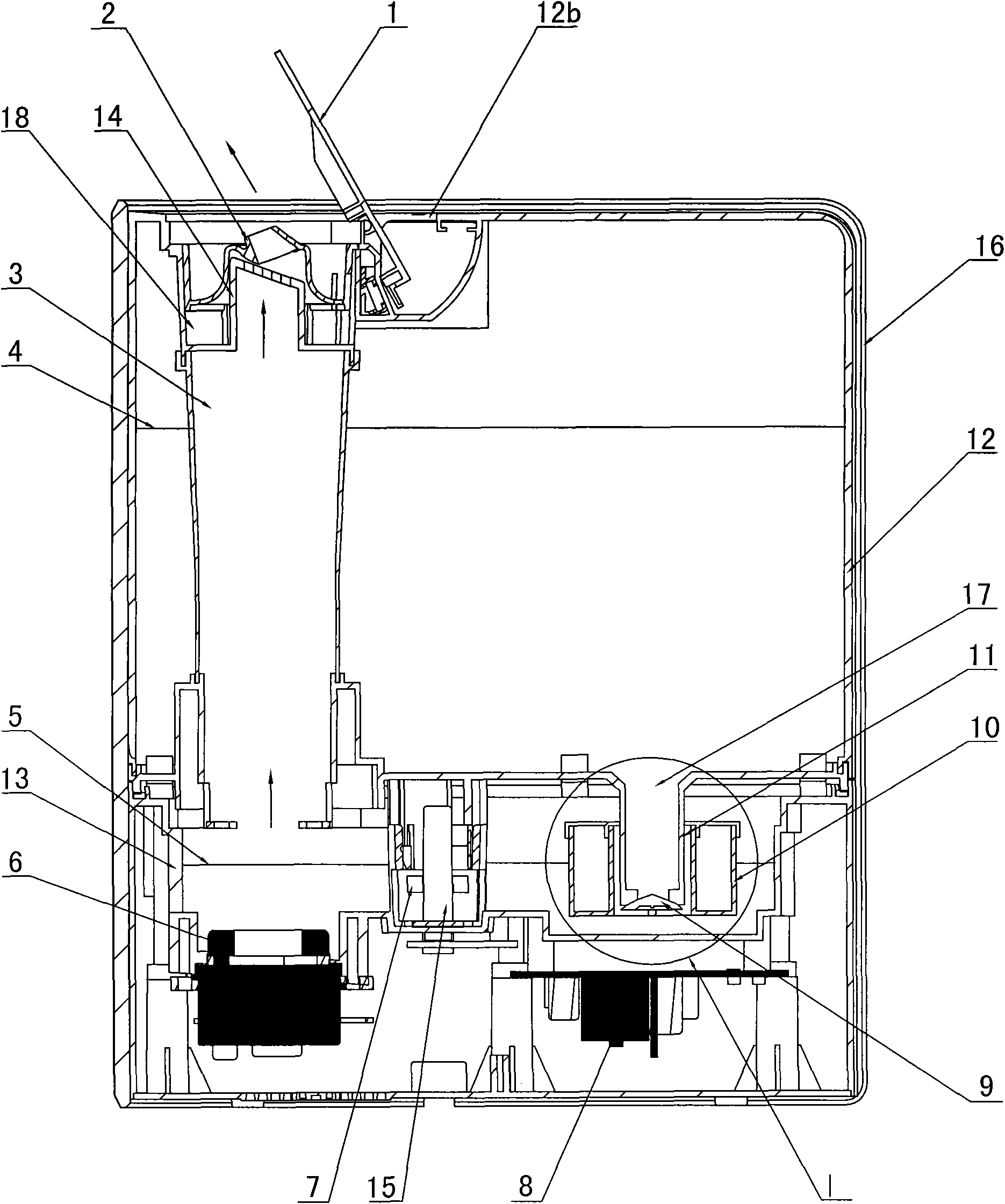
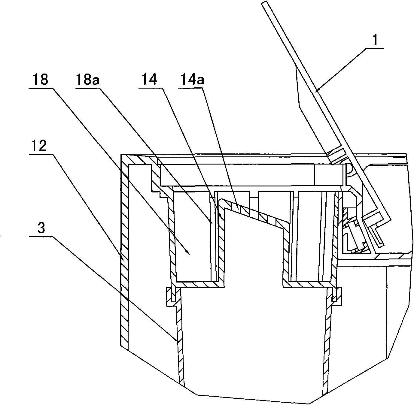
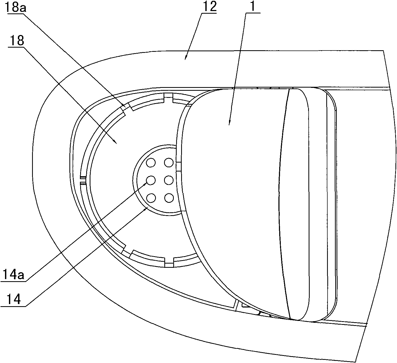
[0037] like Figure 1 to Figure 5 As shown, the top-filling humidifier of the present invention includes a water tank 12, a water tank 13, a transducer 6 and a spray port 14a, wherein the water tank 12 is installed above the water tank 13, and the water tank 12 and the water tank 13 are both accommodated in the shell 16 .

[0038]The top plate 12b of water tank 12 is partly recessed downwards to form a water-filling tank 18. The side wall of water-filling tank 18 has a grid-shaped water-filling port 18a communicating with water tank 12, and water is added in water tank 12 through water-filling port 18a. A water outlet 17 is provided at the bottom of the water tank 12, and the water outlet 17 communicates with the water tank 13 through a water level control device.

[0039] See Figure 4 , the water level control device is made up of water pipe 11, first piston part 9 and buoyancy part 10, and water pipe 11 is vertically arranged, and its upper end pipe mouth is communicated ...

Embodiment 2

[0048] like Figure 6 to Figure 9 As shown, the difference from Embodiment 1 is that the water tank 12 is detachably installed above the water tank 13, and a valve assembly for preventing liquid from flowing out of the tank is provided at the upper end of the water pipe 11. The valve assembly includes a sealing part 11b arranged on the inner wall of the water diversion pipe 11, a second piston part 19 matched with the sealing part 11b, and a top post 20 pierced in the water diversion pipe 11. The upper end of the top post 20 is connected to the second The piston parts 19 are connected to each other, and the lower end protrudes from the water diversion pipe 11 to connect with the lower cover plate 10d of the buoyancy part. In addition, the distance between the sealing portion 11 b and the inner bottom surface of the water tank 13 is smaller than the distance between the second piston portion 19 and the inner bottom surface of the water tank 13 .

[0049] In this way, when the ...

Embodiment 3

[0053] like Figure 10 and Figure 11 As shown, the difference from Embodiment 2 is that the top post 20 includes an upper top post 20a and a lower top post 20b which are in contact with each other up and down, and the upper top post 20a is supported by a support frame 21 arranged in the water diversion pipe 11. 9 and the second piston portion 19 are respectively provided on the upper top post 20a and the lower top post 20b. The buoyancy part 10 is separated from the water tank 12 by decomposing the top column 20 in the second embodiment into two parts. When mentioning water tank 12 to add water like this, water tank 12 becomes comparatively light.


PUM


Abstract

The invention discloses an upper water-adding humidifier. The upper water-adding humidifier comprises a water tank, a water trough, a water level control device, an energy converter and a spray nozzle, wherein the water tank is arranged above the water trough; a water adding port and a water discharging port are formed on the upper part and at the bottom of the water tank respectively; the water level control device is arranged at the water discharging port, and comprises a water leading pipe, a first piston part and a floating part; a mouth at the upper end of the water leading pipe is communicated with the water discharging port of the water tank; a mouth at the lower end of the water leading pipe is stretched into the water trough; the first piston part and the floating part are positioned in the water trough and connected with each other; the first piston part is positioned below the water leading pipe and matched with the mouth at the lower end of the water leading pipe; and the floating part is sleeved on the water leading pipe in a movable manner. The water level control device of the water-adding humidifier has a simple structure and low cost, so that the cost of the humidifier is lowered.

Description

technical field [0001] The invention relates to a humidifier for humidifying by means of water dispersed in the air, in particular to a top-filling humidifier. Background technique [0002] With the improvement of people's living conditions, the requirements for the comfort of the living environment are getting higher and higher. Air humidity is one of the important factors affecting the comfort, especially in the northern regions and places where air conditioners are used for a long time, so humidifiers are becoming more and more popular. It has become an essential small appliance for many families. However, most humidifiers on the market are bottom-filling humidifiers. The water inlet and water outlet of the bottom-filling humidifier are all located at the bottom of the water tank to maintain the water in the tank by utilizing the pressure difference between the air pressure in the water tank and the atmospheric pressure. It will not flow out along the gap between the bot...

Claims


Application Information

Patent Timeline
IPC IPC(8): F24F6/14F24F11/02F16K31/18
Inventor 杨洪永黄家峰
Owner GREE ELECTRIC APPLIANCES INC
Why Eureka
Try Eureka