Alternating current LED light-emitting device
A technology for light-emitting devices and LED chips, which is applied to lighting devices, electroluminescent light sources, components of lighting devices, etc. Low, light output remains stable
Inactive Publication Date: 2012-05-23
SICHUAN SUNFOR LIGHT +1
View PDF7 Cites 22 Cited by
- Summary
- Abstract
- Description
- Claims
- Application Information
AI Technical Summary
Problems solved by technology
However, the processing of this kind of AC LED chip is difficult, and the integration of a huge number of microchips in a small substrate space will lead to problems such as poor heat dissipation.
Method used
View moreImage
Smart ImageViewing Examples
Examples
Embodiment 1-12
[0032] Table 1
[0033]
Login to View More PUM
 Abstract
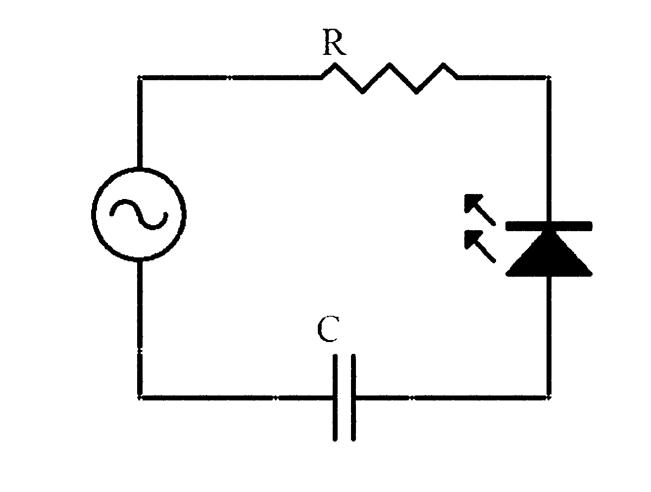
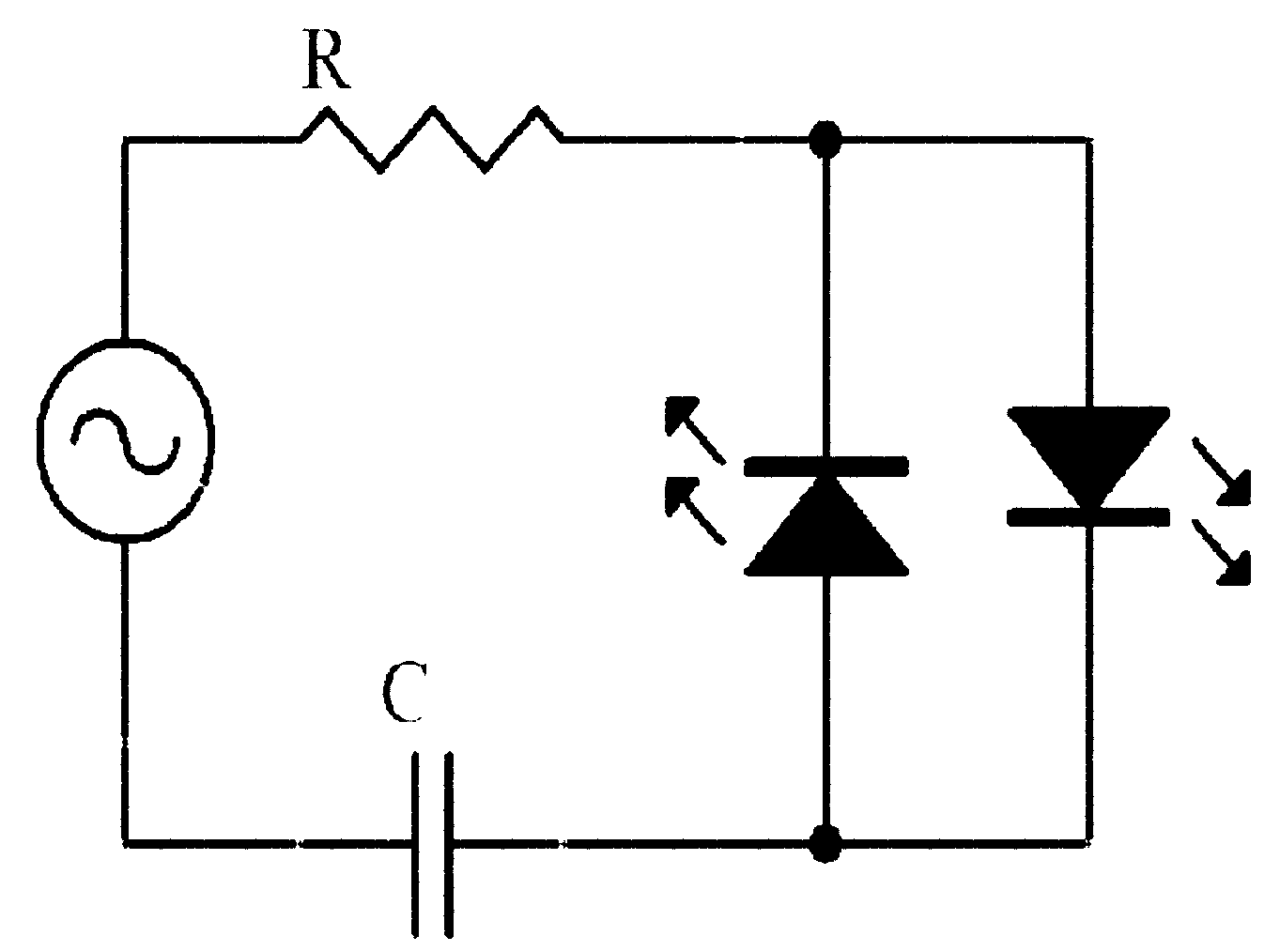
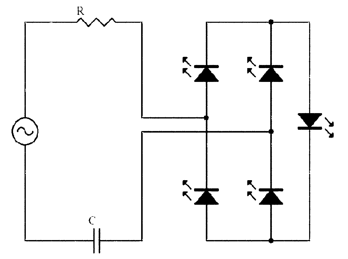
The invention relates to an alternating current LED light-emitting device, belonging to the LED manufacture technology field. The invention is aimed at solving a stroboscopic problem under alternating current power supply with low cost and problems of poor heat radiation and the like caused by microchip integration. A technical scheme of the present invention is as follows: an LED light-emitting unit comprises an LED chip and light-emitting material capable of emitting light under excitation of the LED chip, the LED light-emitting unit is characterized in that: an light-emitting life of the light-emitting material is 1 to 100 ms, the LED chip is the LED chip only comprising an light-emitting PN knot, and the LED light-emitting unit employs alternating current with frequency which is not larger than 100 Hertz for driving. The LED light-emitting device does not use a present alternating current LED chip which is integrated by a plurality of microcrystallites but uses a traditional single PN knot LED chip, fluctuation of luminance is not large in an alternating current period, the stroboscopic problem caused by an alternating current power supply is solved, production is simple, and cost is low.
Description
technical field [0001] The invention relates to an AC LED light emitting device, which belongs to the technical field of AC LED light emitting device manufacturing. Background technique [0002] At present, LED is used in lighting, display, backlight and other fields, and has attracted widespread attention as the most promising next-generation lighting method due to its advantages of energy saving, durability, and pollution-free. Traditional LED chips use DC as the driving current. However, at present, whether it is household, industrial, commercial or public electricity, most of them are provided by industrial frequency AC. Therefore, when using LEDs for lighting and other purposes, a rectifier transformer must be attached to convert AC to DC. , to ensure the normal operation of the LED. However, in the process of AC-DC conversion, there is a power loss of up to 15-30%. At the same time, the conversion device not only has a short service life, but also costs a lot. [000...
Claims
Login to View More Application Information
Patent Timeline
 Patent Type & Authority Applications(China)
IPC IPC(8): H01L33/50F21V23/00F21Y101/02
CPCH05B33/0809H01L33/502H01L33/50F21V23/00H05B33/0803H05B45/00H05B45/37
Inventor 张洪杰张明李成宇赵昆李东明张立
Owner SICHUAN SUNFOR LIGHT
Features
- R&D
- Intellectual Property
- Life Sciences
- Materials
- Tech Scout
- Unparalleled Data Quality
- Higher Quality Content
- 60% Fewer Hallucinations
Learn More Browse by: Latest US Patents, China's latest patents, Technical Efficacy Thesaurus, Application Domain, Technology Topic, Popular Technical Reports.
© 2025 PatSnap. All rights reserved.Legal|Privacy policy|Modern Slavery Act Transparency Statement|Sitemap|About US| Contact US: help@patsnap.com


