Laser driving circuit stabilizing extinction ratio
A technology for driving circuits and lasers, used in lasers, laser parts, semiconductor lasers, etc., can solve problems such as improving the misjudgment rate of symbols, and achieve the effects of simple circuits, strong practicability, and reliable constraints
- Summary
- Abstract
- Description
- Claims
- Application Information
AI Technical Summary
Problems solved by technology
Method used
Image
Examples
Embodiment 1
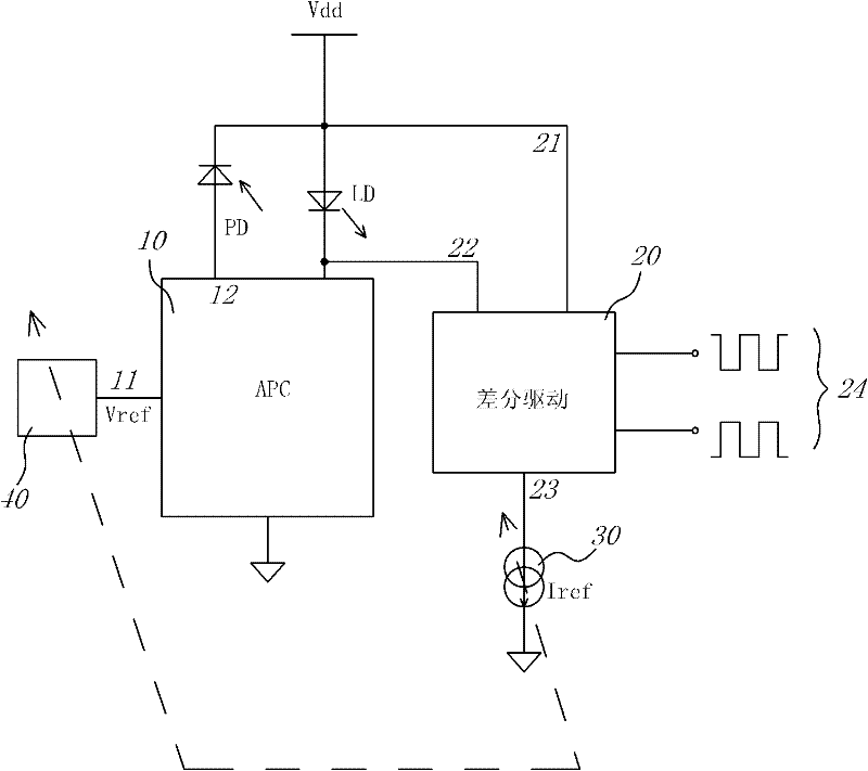
[0032] figure 1 It is a schematic diagram of the first embodiment of the present invention; the power adjustment module 10 is connected in series between the cathode of the laser LD and the ground, and then connected to the anode of the backlight diode PD through a voltage sampling terminal 12, and connected to a reference voltage module through a reference voltage terminal 11 40. The voltage value of the voltage sampling terminal 12 is proportional to the photocurrent of the backlight diode PD.
[0033] A differential drive module 20, the first and second differential drive terminals 21, 22 are respectively connected to the positive and negative electrodes of the laser LD; the differential drive module 20 has a common mode current terminal 23 to the ground, and a reference current to the ground Determined by the reference current module 30.
[0034] In actual work, the reference voltage module 40 outputs a reference voltage Vref to the reference voltage terminal 11 of the power ad...
Embodiment 2
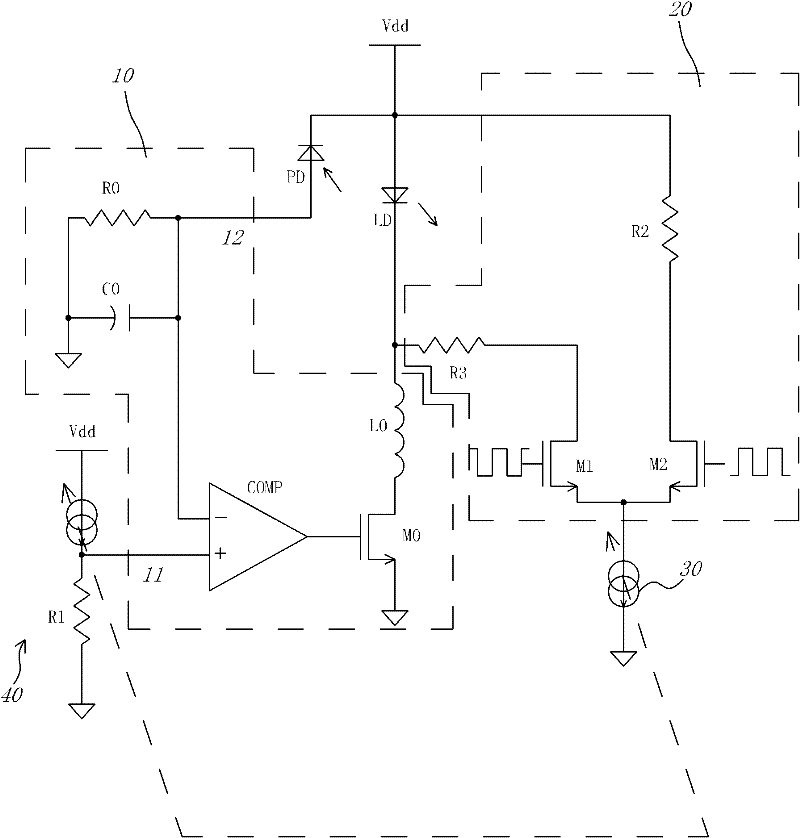
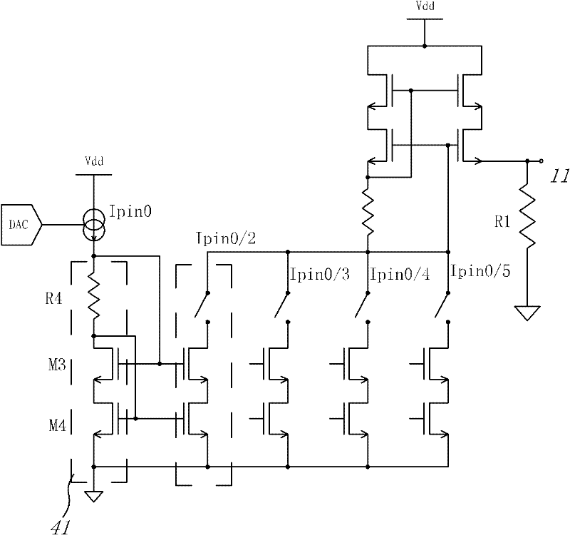
[0051] Such as figure 2 , A schematic diagram of the circuit of the second embodiment of the present invention; image 3 Yes figure 2 The structure of the reference voltage module 40 in the embodiment is schematic; Figure 4 Yes figure 2 The structure of the reference current module 30 in the embodiment is schematic; the second embodiment will be described with reference to the three figures:
[0052] The power adjustment module 10 has a sampling loop, including a resistor R0 and a capacitor C0 connected in parallel, which are connected between the anode of the backlight diode PD and the ground; the current flowing through the backlight diode PD has a sampling voltage on R0, and the sampling voltage is at the voltage The sampling terminal 12 is connected to the negative input terminal of a high-speed comparator COMP.
[0053] The positive input terminal of the high-speed comparator COMP is the reference voltage terminal 11, and its output terminal is connected to the gate of a r...
PUM
 Abstract
Description
Claims
Application Information
 - R&D Engineer
- R&D Manager
- IP Professional
- Industry Leading Data Capabilities
- Powerful AI technology
- Patent DNA Extraction
Browse by: Latest US Patents, China's latest patents, Technical Efficacy Thesaurus, Application Domain, Technology Topic, Popular Technical Reports.
© 2024 PatSnap. All rights reserved.Legal|Privacy policy|Modern Slavery Act Transparency Statement|Sitemap|About US| Contact US: help@patsnap.com


