Supercharge Your Innovation With Domain-Expert AI Agents!

Enabling control circuit

A technology for controlling circuits and loops, which is applied in the field of enabling control circuits, can solve the problems of difficult enabling control circuits and reduce the precision of enabling control, and achieve the effects of improving precision, preventing noise, and reducing layout area

Active Publication Date: 2012-05-23
WUXI CHIPOWN MICROELECTRONICS
View PDF5 Cites 1 Cited by
  • Summary
  • Abstract
  • Description
  • Claims
  • Application Information

AI Technical Summary

Problems solved by technology

The above constraints and requirements make it very difficult to design an enabling control circuit with excellent performance.
[0005] The power supply voltage range of traditional enable control circuits currently used in portable products is usually between 2.5V and 6V. In this range, the turning point level of enable usually changes with the power supply voltage, which reduces to enable control precision

Method used


Image

  • Enabling control circuit
  • Enabling control circuit
  • Enabling control circuit

Examples


Embodiment Construction

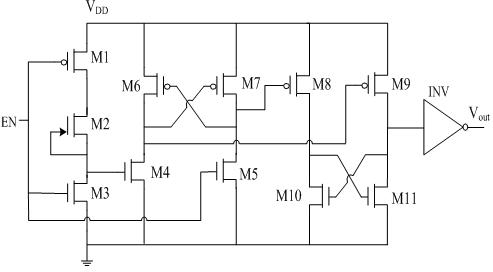
[0021] The present invention will be further described below in conjunction with the accompanying drawings and specific embodiments. The enabling control circuit of the present invention is as attached figure 1 shown. It includes a first input stage, a second level comparison stage, a third level comparison stage and a fourth output shaping stage. The first input stage includes an enhancement PMOS transistor M1, a depletion N-channel transistor M2 and an enhancement NMOS transistor M3. In this input stage, the gate and source of the depletion mode transistor M2 are connected together, so the gate-source voltage difference is zero. When the voltage at the input EN terminal is lower than the breakover voltage, the voltage at the source terminal of M2 is higher than the voltage at the EN terminal. At the turning point of the output voltage, the current of transistor M3 is:

[0022]

[0023] And the current of M2 is equal to this, which is:

[0024]

[0025] Order I 2 =...


PUM


Abstract

The invention discloses an enabling control circuit. The enabling control circuit comprises M1-M11 transistors and an inverter INV, wherein M1, M6, M7, M8 and M9 transistors are PMOS (P-channel Metal Oxide Semiconductor) enhancement transistors; M2 is an N-type channel depletion transistor; and M3, M4, M5, M10 and M11 are NMOS (N-Channel Metal Oxide Semiconductors). The enabling control circuit is characterized in that the gate source voltage of the N-type channel depletion transistor is constant, thus the saturation current is constant. Therefore, enabling input breakover levels are substantially equal in different power voltages, and the defect that the enabling breakover levels change greatly along with change of the power voltages when the traditional enabling control circuit is in different power voltages is overcome. The enabling control circuit is simple in structure and easy to realize.

Description

[0001] technical field [0002] The invention belongs to the technical field of analog integrated circuits, and in particular relates to an enabling control circuit. When the input terminal voltage is higher than a certain value, the chip is turned on; when it is lower than a certain value, the chip is turned off. Background technique [0003] With the rapid development of the semiconductor industry, a large number of chips have emerged, which have penetrated into various fields and industries, bringing great convenience to our life and work. No matter what type of chip, including digital IC, analog IC or complex SOC, etc., they often need to enable the control signal, according to the size of the external enable signal to determine whether the circuit is turned off or on, so the enable control circuit application is very common. [0004] Because the enable control circuit needs to control the entire chip to turn off or on, and of course also includes the general bias circ...

Claims


Application Information

Patent Timeline
Patent Type & Authority Applications(China)
IPC IPC(8): H02M1/36
Inventor 张立新谢凌寒陈健易扬波周飙李海松张韬武家中
Owner WUXI CHIPOWN MICROELECTRONICS
Features
  • R&D
  • Intellectual Property
  • Life Sciences
  • Materials
  • Tech Scout
  • Unparalleled Data Quality
  • Higher Quality Content
  • 60% Fewer Hallucinations
Learn More