Work transfer apparatus for press machine, and work transfer unit

A technology for conveying devices and presses, which is applied in the direction of feeding devices, positioning devices, storage devices, etc., can solve the problems of rising manufacturing costs, increasing types, and complex structures of workpiece conveying devices, and achieve simplified structures, improved maintainability, increased The effect of a large range of movement

Inactive Publication Date: 2012-05-23
KOMATSU LTD +1
View PDF6 Cites 5 Cited by
  • Summary
  • Abstract
  • Description
  • Claims
  • Application Information

AI Technical Summary

Problems solved by technology

Therefore, the types of parts increase and the structure becomes complicated, which leads to an increase in the manufacturing cost of the workpiece transfer device

Method used


Image

  • Work transfer apparatus for press machine, and work transfer unit
  • Work transfer apparatus for press machine, and work transfer unit
  • Work transfer apparatus for press machine, and work transfer unit

Examples


no. 1 approach 〕

[0065] First, use figure 1 The overall structure of the transfer press (press) 1 according to the first embodiment of the present invention will be described.

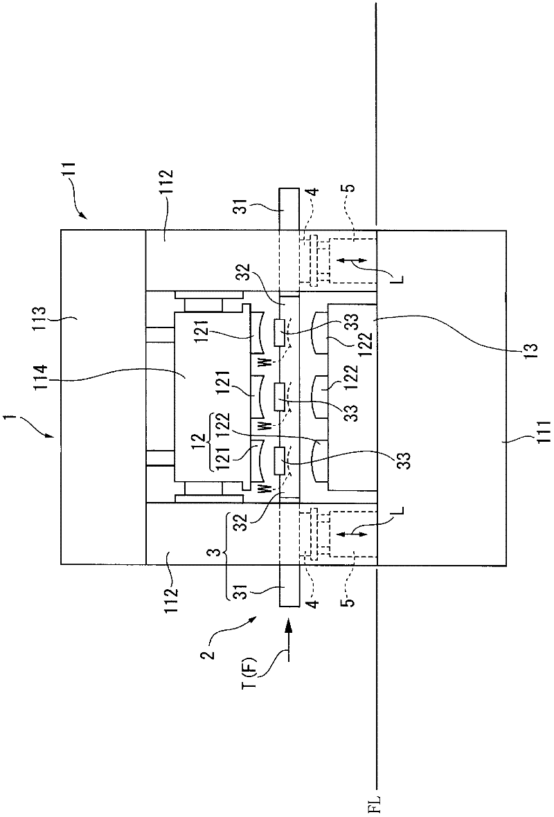
[0066] The multi-station press 1 has: a press main body 11, which has a base 111, a column 112, a crown portion 113, and a slider 114; a mold 12, which has an upper mold 121 and a lower mold 122; a movable cross brace 13, and The transfer press 1 as described above is provided with a transfer feeder (work transfer device) 2 .

[0067] In the press main body 11, a base 111 serving as a base of the transfer press 1 is provided under the floor FL, and upright columns 112 are erected at four corners of the base 111, which is substantially rectangular in plan view (see Figure 6 and Figure 7 ). figure 1 The middle figure shows two upright columns 112 erected on the upstream and downstream sides of the conveyance direction of the workpiece W (hereinafter referred to as the workpiece conveyance direction) T. As shown in F...

no. 2 approach 〕

[0111] Below, based on Figure 8 ~ Figure 10 A second embodiment of the present invention will be described.

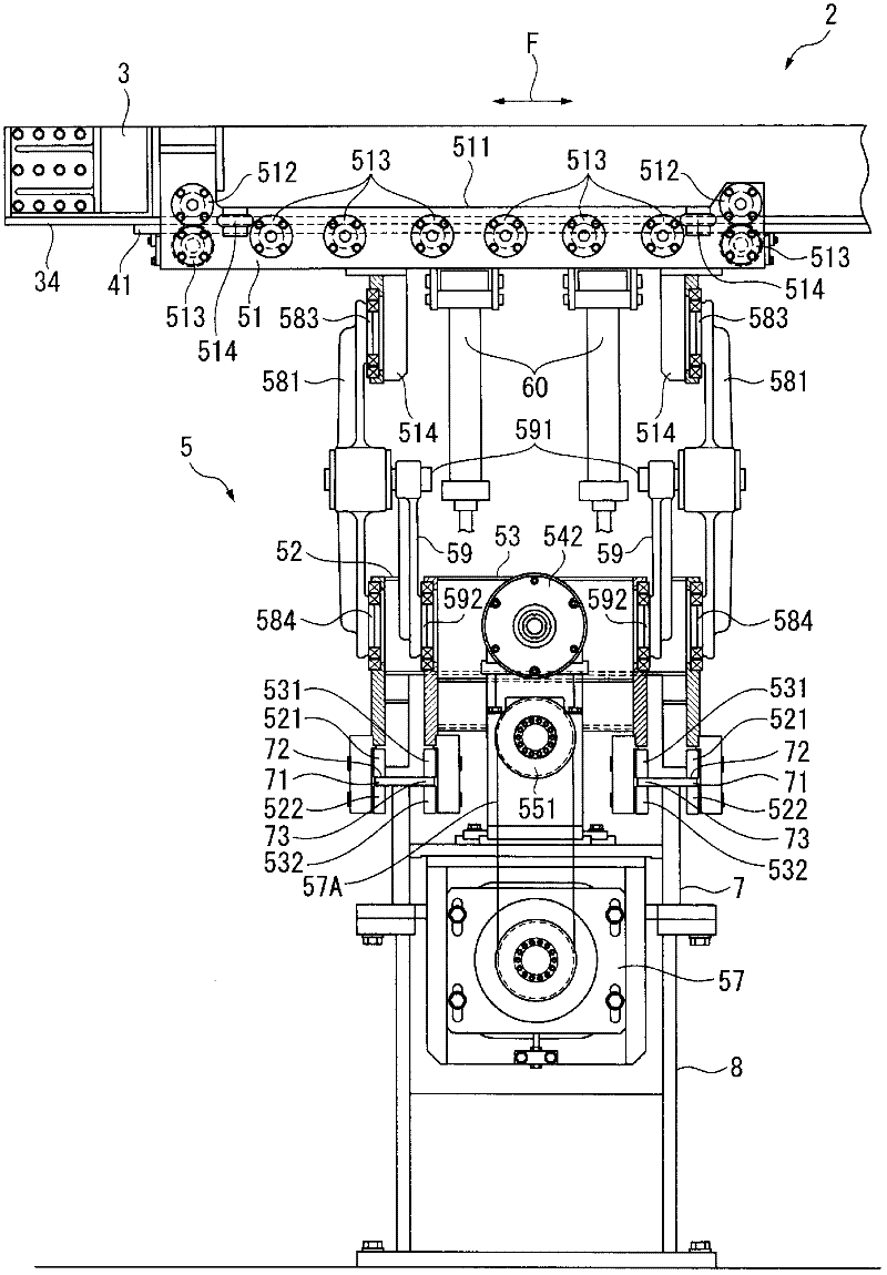
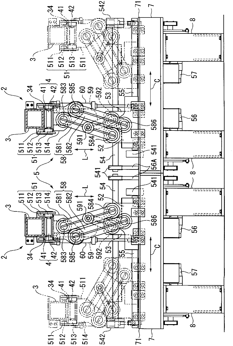
[0112] In the first and second carrying devices 52 and 53 of the first embodiment described above, the upper guide rollers 521 and 531 and the lower guide rollers are provided so as to sandwich the first and second guide parts 72 and 73 of the guide rail 71 up and down. 522, 532, but in this embodiment, side guide rollers 523, 533 that abut against the side end surfaces of the guide rail 71 are further provided to make the first and second carrying devices 52, 53 move in the clamping direction C Be guided more reliably. In addition, it goes without saying that the above-mentioned side guide rollers 523 and 533 may also be used in the first embodiment.

[0113] In addition, in the first embodiment, each link 581, 582 constituting the parallel link 58 has a structure in which a rib is erected in the longitudinal direction at the center of the flat portion, but the str...

no. 3 approach

[0118] In the aforementioned first embodiment, the linear motor 4 for feeding is provided as the feeding drive mechanism of the rod 3 , and the rod 3 is reciprocated in the feeding direction F by the linear motor 4 for feeding.

[0119] In contrast, in the third embodiment, as Figure 11 As shown, the timing belt mechanism 9 is used as the feed drive mechanism to reciprocate the rod 3 in the feed direction F, which is different from the first embodiment described above.

[0120] Specifically, the timing belt mechanism 9 is provided between the rod 3 and the support portion 51 , and the entire timing belt mechanism 9 is supported by the support portion 51 . The timing belt mechanism 9 is configured to include: a timing belt 91 having a terminal end fixed to the rod 3 and having both ends fixed between the rod 3 and the support portion 51 ; and guide pulleys 92 , 93 for guiding the timing belt 91 . , the driven pulley 95 sharing the rotating shaft 94 with the guide pulley 93, t...


PUM


Abstract

A work transfer apparatus (2) is provided with a feed drive mechanism (4), which drives a transfer bar (3) in the work transfer direction, and a lift clamp drive mechanism (5), which drives the transfer bar (3) in the lift direction (L) and the clamp direction (C). The lift clamp drive mechanism (5) is provided with: a supporting section (51) for the transfer bar (3); first and second carriers (52, 53) which can move in the clamp direction (C); first and second carrier drive mechanisms (54, 55, 56, 57) which drive each of the carriers (52, 53); parallel links (58) which rotatably connect the first carrier (52) with the supporting section (51); and a drive link (59) which rotatably connects one of the parallel links (58) with the second carrier (53). A first guide section (72) which guides the first carrier (52) and a second guide section (73) which guides the second carrier (53) are parallel to each other and are shifted from each other in the work transfer direction.

Description

technical field [0001] The present invention relates to a workpiece conveying device and a workpiece conveying unit of a press machine for conveying a workpiece. Background technique [0002] Conventionally, in a transfer press having a plurality of processing tables in a press main body, a workpiece transfer device that sequentially transfers a workpiece between each processing step is provided. [0003] This workpiece transfer device has a pair of transfer rods arranged in parallel to the transfer direction of the workpiece, and the transfer rods are detachably equipped with a plurality of workpiece holding mechanisms corresponding to the upper die and the lower die. The transfer rod performs a three-dimensional motion consisting of motions in the following directions, that is, motions in the feed direction and return direction that reciprocate in the same feed direction as the workpiece conveying direction; the reciprocating motion in the lifting direction (up and down di...

Claims


Application Information

Patent Timeline
Patent Type & Authority Applications(China)
IPC IPC(8): B21D43/05
CPCB21D43/05B21D24/005
Inventor 西田宪二守安隆史明石秀利
Owner KOMATSU LTD
Why Eureka
Try Eureka