Operational amplifier having improved slew rate

A technology of operational amplifiers and slew rates, applied in amplifiers, amplifiers with semiconductor devices/discharge tubes, DC-coupled DC amplifiers, etc., can solve problems such as input signal limitations, amplifier output distortion, etc.

Inactive Publication Date: 2012-05-23
INDIAN INSTITUTE OF TECHNOLOGY BOMBAY
View PDF5 Cites 2 Cited by
  • Summary
  • Abstract
  • Description
  • Claims
  • Application Information

AI Technical Summary

Problems solved by technology

In other words, if the frequency of the input signal exceeds the slew-rate limit of the amplifier, the slew-rate limitation creates non-linear effects, which can severely distort the output of the amplifier
Thus, the frequency of the input signal is usually limited by the capabilities of the amplifier during circuit design

Method used


Image

  • Operational amplifier having improved slew rate
  • Operational amplifier having improved slew rate
  • Operational amplifier having improved slew rate

Examples


Embodiment Construction

[0019] In the following detailed description, reference is made to the accompanying drawings which form a part hereof. In the drawings, similar symbols typically identify similar components, unless context dictates otherwise. The exemplary embodiments described in the detailed description, drawings, and claims are not limiting. Other embodiments may be utilized, and other changes may be made, without departing from the spirit or scope of the subject matter presented here. It should be understood that the aspects of the present disclosure generally described herein and illustrated in the drawings can be arranged, substituted, combined, divided and designed in many different configurations both explicitly and implicitly disclosed herein.

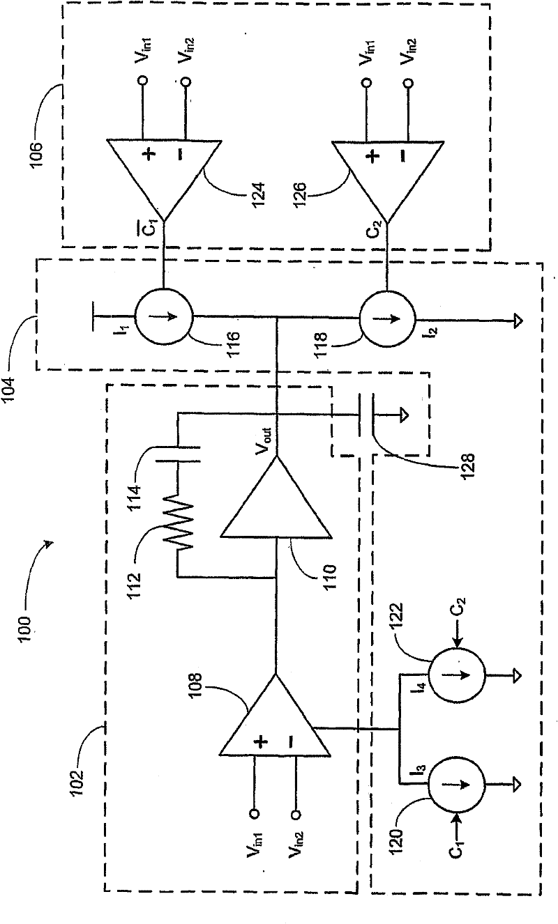
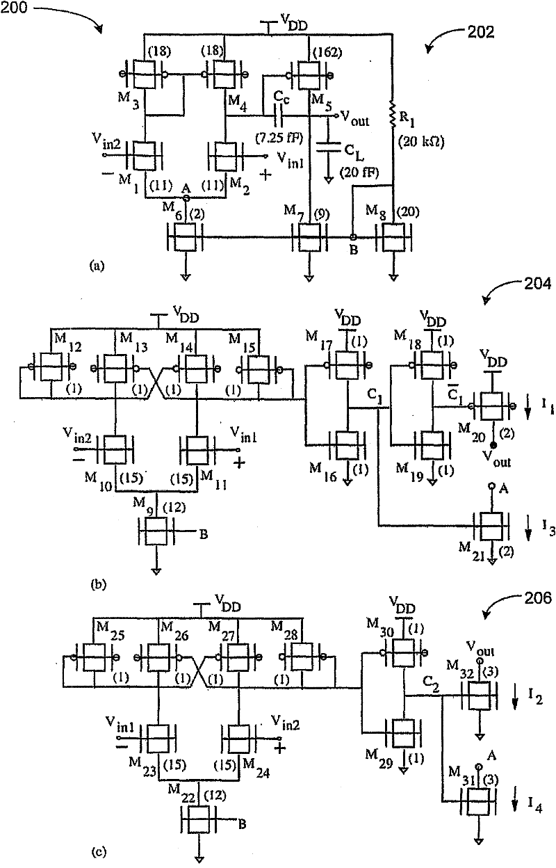
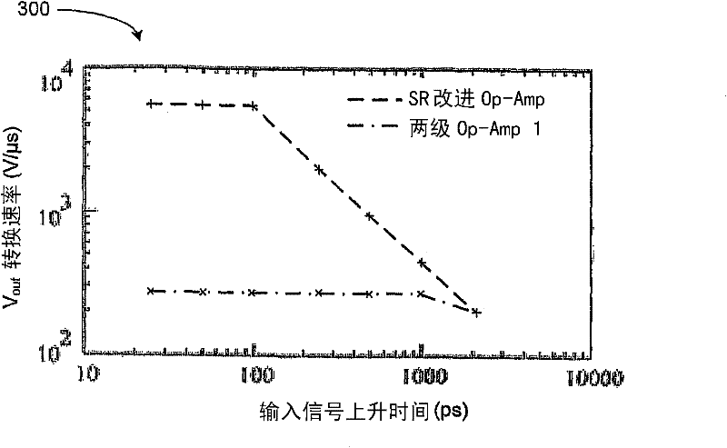
[0020] The present application provides an operational amplifier with high slew rate while maintaining low power overhead and essential performance metrics. In one embodiment, the operation of the circuit relies on detecting the onset of the...


PUM


Abstract

A slew rate improved operational amplifier circuit is provided to improve the slew rates of an operational amplifier with minimal sacrifices in power dissipation and other operational amplifier parameters. To improve the slew rates of operational amplifiers, additional current sources are activated when a slewing operation is detected. The detection of slewing operations and the activation of current sources upon detection can be implemented using two comparator circuits - one for a positive slewing operation, and one for a negative slewing operation. A sub-45nm FinFET implementation of this slew rate improvement concept was implemented and compared against slew rate optimized individual two-stage operational amplifiers. Simulations show that slew rates were significantly improved by the implementation of the comparator circuits (5590 V / [mu]s vs. 273 V / [mu]s), with minimal increases in power dissipation (78 [mu]W vs. 46 [mu]W).

Description

[0001] Cross References to Related Applications [0002] This application claims priority from Indian Patent Application Serial No. 542 / MUM / 2010 filed March 2, 2010, the entire contents of which are hereby incorporated by reference. This application also claims priority to corresponding US Patent Application Serial No. 12 / 764,294, filed April 21, 2010, the entire contents of which are incorporated herein by reference. Background technique [0003] A common two-stage op amp consists of an input stage and a second stage. The input stage is usually a differential amplifier with a transconductance characteristic, producing an output current from a differential voltage input. Transconductance is typically very high, so a fairly small input voltage may be sufficient to cause the input stage to saturate, resulting in a constant current output. [0004] The second stage receives the current output from the input stage, where frequency compensation is implemented. The low-pass chara...

Claims


Application Information

Patent Timeline
IPC IPC(8): H03F3/45
CPCH03F3/45475H03F2203/45248H03F1/0222H03F3/45569
Inventor 拉杰什·A·塔克尔马扬克·斯里瓦斯塔瓦马里亚姆·舒贾依·巴吉尼迪内希·K·夏尔马V·拉姆戈帕尔·拉奥马赫什·B·帕希尔
Owner INDIAN INSTITUTE OF TECHNOLOGY BOMBAY
Why Eureka
Try Eureka