
Common mode filter

A common-mode filter, capacitor technology, used in impedance networks, electrical components, multi-terminal pair networks, etc.

Active Publication Date: 2012-05-23
ELMEC
View PDF7 Cites 5 Cited by
  • Summary
  • Abstract
  • Description
  • Claims
  • Application Information

AI Technical Summary

Problems solved by technology

[0003] Especially in the recent high-speed serial transmission (serial transmission) technology, since the transmission speed reaches the GHz frequency range, the speed is faster and the wavelength is shorter, so The probability that the wavelength coincides with an integer multiple of the length of the circuit pattern becomes high. For this reason, the circuit pattern is used as an antenna to radiate signals into space, resulting in the problem of electromagnetic radiation noise
[0004] In addition, in high-speed serial transmission, differential lines are used in most cases, so the electromagnetic field is combined between the differential lines, and it is difficult to radiate to the outside
[0005]However, the slight asymmetry of the differential line and the slight phase shift in the IC etc. lead to common mode noise which is in the differential line They are transmitted in the form of in-phase signals, and because there is no connection between differential lines, they are easy to radiate to the outside, thus easily forming electromagnetic radiation noise

Method used


Image

  • Common mode filter
  • Common mode filter
  • Common mode filter

Examples


Embodiment Construction

[0072] Specific embodiments of the common mode filter involved in the present invention will be described below with reference to the drawings.

[0073] First, the lumped constant differential delay line which is the basis of the common mode filter according to the present invention will be described.

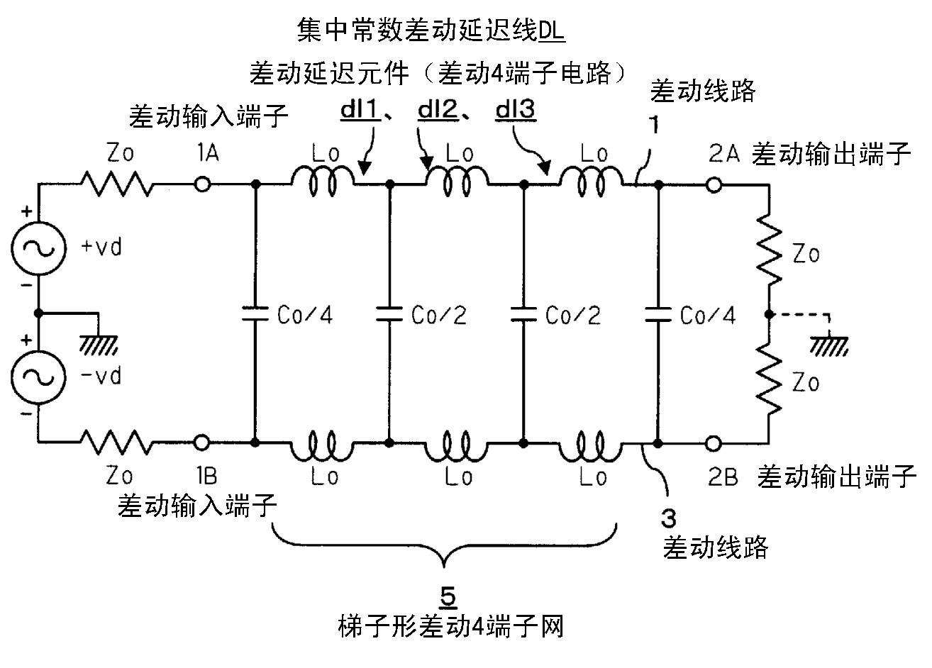
[0074] figure 1 It is a circuit diagram showing an example of a lumped constant differential delay line used in the common mode filter of the present invention.

[0075] figure 1 A ladder-shaped differential 4-terminal net 5 is formed on the differential lines 1, 3 between the middle differential input terminals 1A, 1B and the differential output terminals 2A, 2B.

[0076] The ladder-shaped differential 4-terminal network 5 is a ladder-shaped combination of passive series elements arranged in series on the above-mentioned differential lines 1, 3 and passive parallel elements arranged in parallel on the above-mentioned differential lines 1, 3 structure.

[0077] In other words, on the ...


PUM


Abstract

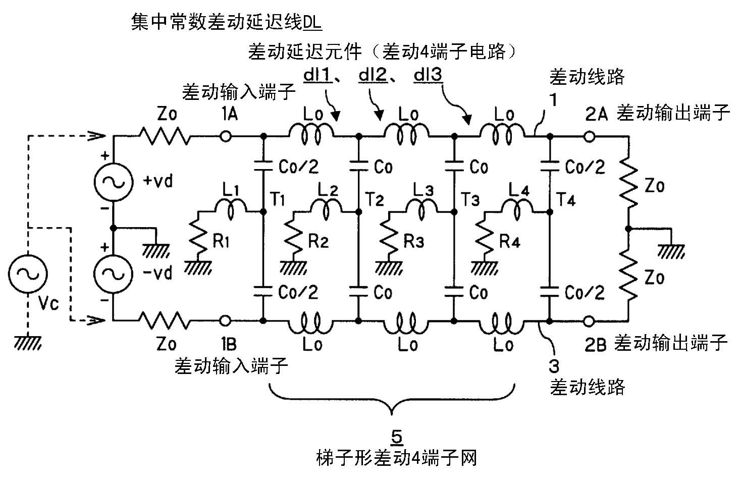
There is provided a common mode filter capable of allowing an ultrahigh speed differential signal to transmit and hardly allowing a common mode noise to transmit, comprising: a lumped-constant differential delay line DL formed by arranging inductors Lo, being passive series elements, and capacitors Co, being passive parallel elements, in a ladder-shaped differential four terminal network composed of the passive series elements and the passive parallel elements arranged in the differential lines 1, 3. In the lumped-constant differential delay line DL, the capacitors Co, being the parallel elements, are formed of two capacitors connected in series equivalent to each other and having same values with each other such as Co / 2 and Co / 2, or Co and Co. Inductors L1 to L4 and resistors R1 to R4 for attenuating the common mode noise are connected between connection points T1 to T4 of the capacitors Co / 2 or Co connected in series, and a ground potential, thus forming a common mode noise attenuating series resonance circuit together with the capacitors Co / 2, Co.

Description

technical field [0001] The present invention relates to a common-mode filter, in particular to a common-mode filter which can block unnecessary common-mode noise while transmitting ultra-high-speed differential signals required for ultra-high-speed differential lines, so as to Avoid causing electromagnetic interference. Background technique [0002] In electronic equipment, noise is a harmful phenomenon, so many solutions for eliminating noise have been proposed in the prior art. [0003] Especially in the recent high-speed serial transmission (serial transmission) technology, since the transmission speed reaches the GHz frequency range, the speed is faster and the wavelength is shortened, so that the wavelength is equivalent to an integer multiple of the length of the circuit pattern. The probability of coincidence becomes high, and therefore, a signal is radiated into the space by using the circuit wiring as an antenna, and a problem of electromagnetic radiation noise ari...

Claims


Application Information

Patent Timeline
Patent Type & Authority Applications(China)
IPC IPC(8): H03H7/06H03H7/09
CPCH03H7/1733H03H7/1725H03H7/427H03H7/1766H03H7/1708H03H7/09H03H7/075
Inventor 龟谷雅明
Owner ELMEC
Learn More