Common mode filter

a filter and common mode technology, applied in the direction of line transmission, current interference reduction, line transmission details, etc., can solve the problems of hardly allowing the transmission signal to be radiated outside, common mode noise having an in-phase signal, electromagnetic radiation noise to occur, etc., to reduce the peak voltage of common mode noise and hardly cause electromagnetic interference to occur.

Active Publication Date: 2014-09-30
ELMEC
View PDF14 Cites 5 Cited by
  • Summary
  • Abstract
  • Description
  • Claims
  • Application Information

AI Technical Summary

Benefits of technology

[0031]In the common mode filter according to an aspect of the present invention,
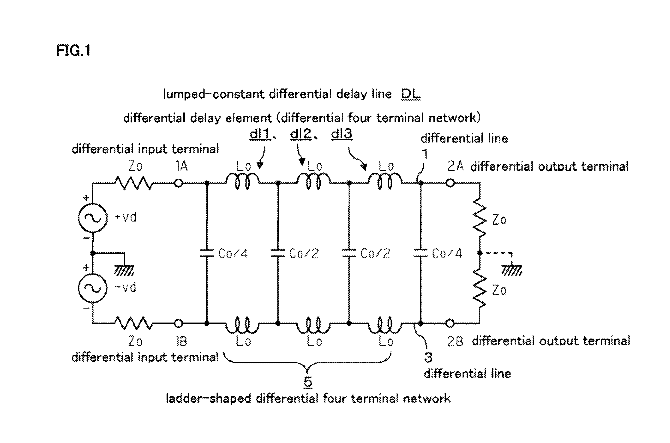
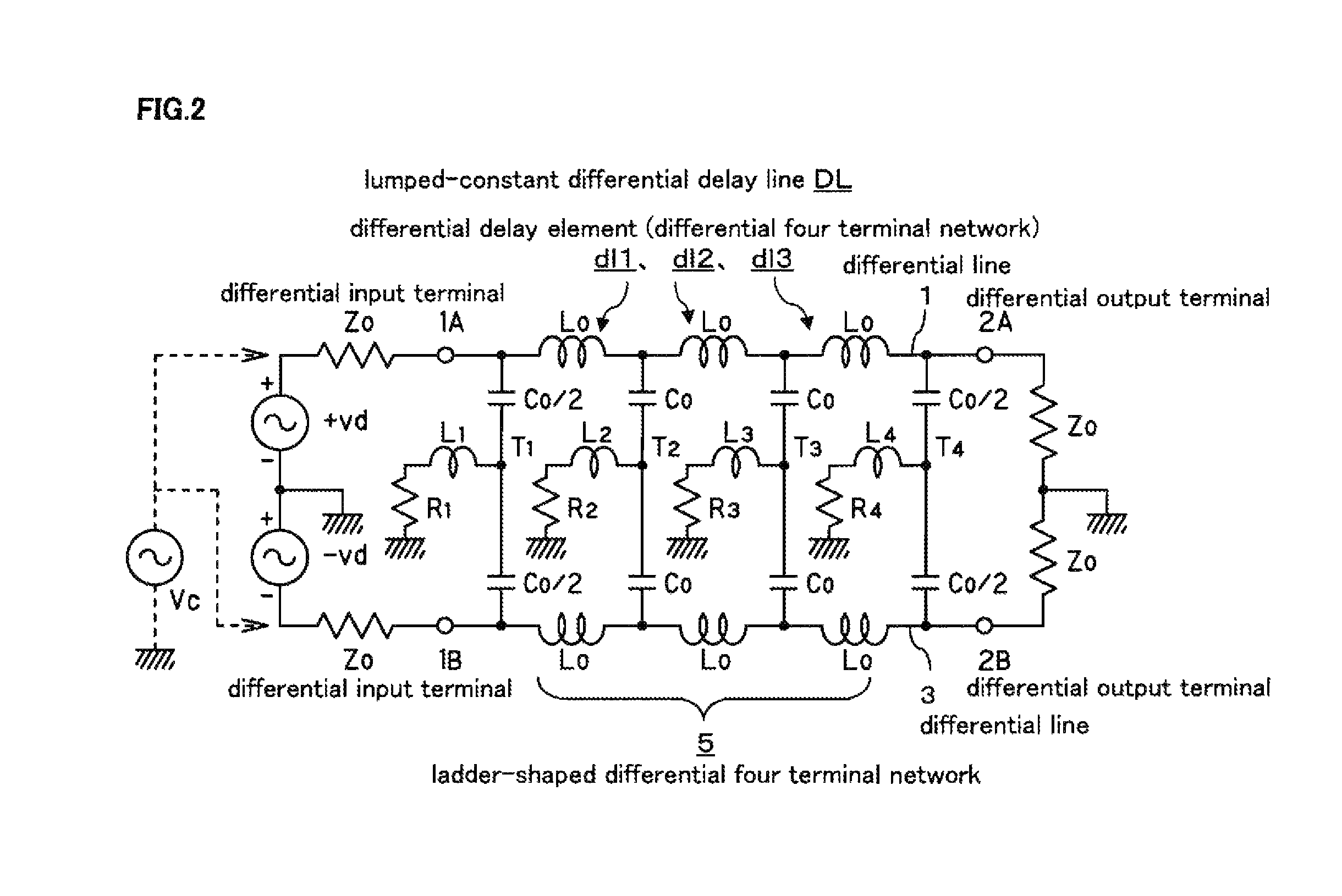
[0032]the lumped-constant differential delay line is used, which is formed by arranging inductors, being passive series elements, and capacitors, being passive parallel elements, wherein the capacitors, being the parallel elements, are formed by two capacitors equivalent to each other, having equal values, and connected in series, and the noise attenuating passive two terminal network is connected between the connection point of the capacitors connected in series and the ground potential, including resistors for attenuating the common mode noise, the series circuit of the inductors and the resistors, or the parallel circuit of the inductors and the resistors. Therefore, a high-speed differential signal can be transmitted, and meanwhile an undesirable common mode noise can be cut off and can be absorbed by resistors, thus reducing the peak voltage of the common mode noise at the input terminal portion and hardly causing the electromagnetic interference to occur.
[0033]In the common mode filter according to an aspect of the present invention, the lumped-constant differential delay line is formed into the constant K-type structure, and therefore the aforementioned effect can be obtained in this constant K-type structure.
[0034]In the common mode filter according to an aspect of the present invention, the lumped-constant differential delay line is formed into the derived m-type structure, and therefore the aforementioned effect can be obtained in this derived m-type structure.
[0035]In the common mode filter according to an aspect of the present invention, the lumped-constant differential delay line is formed into the all pass type structure, and therefore the aforementioned effect can be obtained in this all pass type structure.
[0036]In the common mode filter according to an aspect of the present invention, the lumped-constant differential delay line and the noise attenuating inductors are formed as differential delay elements of one section, and a plurality of differential delay elements are arranged in the differential line in series in a ladder shape, thus forming a plurality of sections, and therefore various filter characteristics can be obtained in addition to the aforementioned effect.

Problems solved by technology

Therefore, there is a problem that the transmission signal is emitted into a space, with a circuit pattern as an antenna, thus causing an electromagnetic radiation noise to occur.
However, in the high-speed serial transmission, differential lines are used in most cases, and therefore coupling of electromagnetic fields occurs between the differential lines, thus hardly allowing the transmission signal to be radiated outside.
However, the common mode noise having an in-phase signal is generated by a slight asymmetry property of the differential lines and a slight phase deviation in IC.
Thus, the electromagnetic radiation noise is easily generated.

Method used


Image

  • Common mode filter
  • Common mode filter
  • Common mode filter

Examples


second embodiment

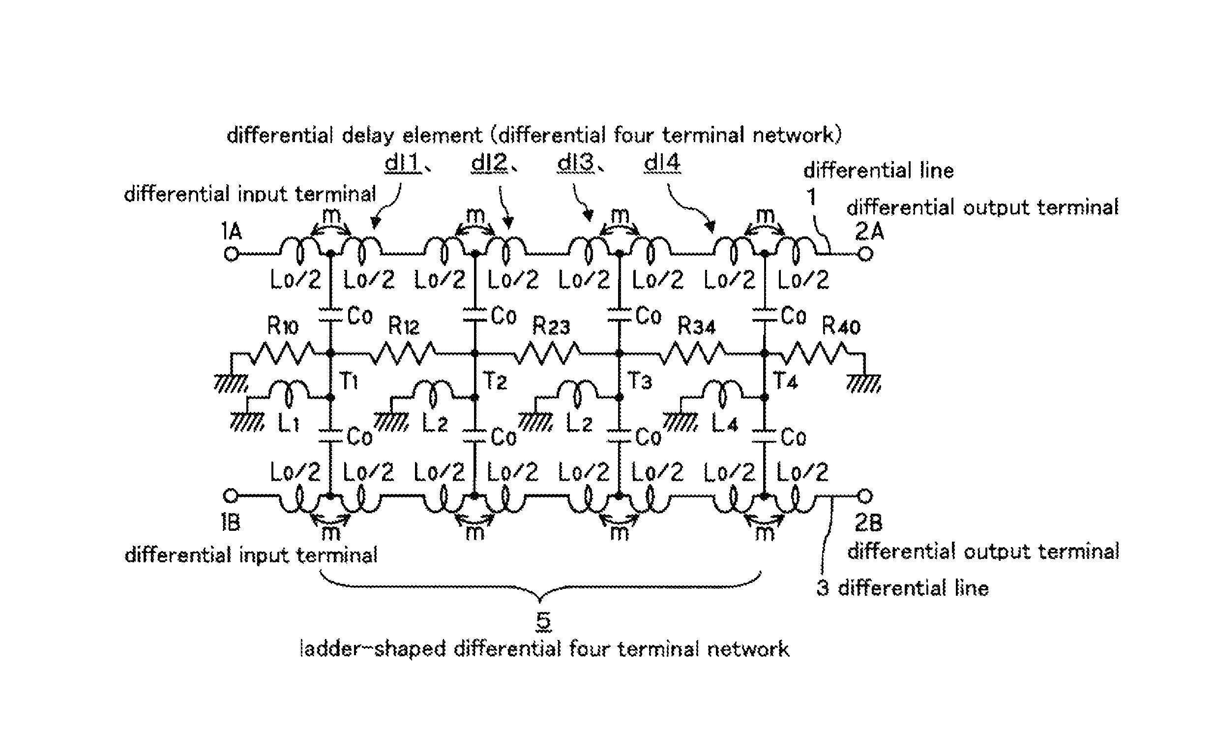
[0087]FIG. 5 shows the common mode filter of the present invention, with a derived mT-type lumped-constant differential delay line composed of four sections as a base.

[0088]Specifically, in each of the four differential delay elements dl1 to dl4, inductors Lo that form the passive series elements are equally divided into two, then the equally divided inductors Lo / 2 are connected in series, and mutual inductive m-coupling is made between them, and connection points of the two equally divided inductors Lo / 2 are connected by a series circuit of the capacitors. The other structure is the same as the structure of FIG. 1.

[0089]In the structure of FIG. 5 as well, the parallel elements of each differential four terminal network are converted to the series circuit of two capacitors Co and Co having two-fold capacitance values, and the aforementioned inductors L1 to L4 for attenuating the common mode noise are connected between the connection points T1, T2, T3, T4 of capacitors Co connected i...

third embodiment

[0102]FIG. 8 shows the common mode filter of the present invention.

[0103]Namely, the all pass lumped-constant differential delay line is composed of four differential delay elements dl1 to dl4, and in each differential delay element dl1 to dl4, inductors Lo that form the passive series elements are equally divided into two, then the equally divided inductors Lo / 2 are connected in series, and mutual inductive m-coupling is made between them. Further, both ends of the inductors Lo / 2 connected in series are bridged by capacitor Ca, and the connection points of both inductors Lo / 2 between the differential lines 1 and 3 are connected by the series circuit of the capacitors Co. The other structure is the same as the structure of FIG. 5.

[0104]With this structure, regarding the inductors that constitute the passive series elements of the ladder-shaped differential four terminal network, the inductors for determining a delay time of one section are expressed by (Lo+2m) equivalently, and the ...


PUM


Abstract

There is provided a common mode filter capable of allowing an ultrahigh speed differential signal to transmit and hardly allowing a common mode noise to transmit, comprising: a lumped-constant differential delay line DL formed by arranging inductors Lo, being passive series elements, and capacitors Co, being passive parallel elements, in a ladder-shaped differential four terminal network composed of the passive series elements and the passive parallel elements arranged in the differential lines 1, 3. In the lumped-constant differential delay line DL, the capacitors Co, being the parallel elements, are formed of two capacitors connected in series equivalent to each other and having same values with each other such as Co / 2 and Co / 2, or Co and Co. Inductors L1 to L4 and resistors R1 to R4 for attenuating the common mode noise are connected between connection points T1 to T4 of the capacitors Co / 2 or Co connected in series, and a ground potential, thus forming a common mode noise attenuating series resonance circuit together with the capacitors Co / 2, Co.

Description

TECHNICAL FIELD[0001]The present invention relates to a common mode filter, and particularly relates to the common mode filter capable of cutting off an undesirable common mode noise and hardly causing an electromagnetic interference to occur, while transmitting an ultrahigh speed differential signal which is propagated through an ultrahigh speed differential line.DESCRIPTION OF RELATED ART[0002]In an electronic device, noise is an undesirable presence, and therefore there are many proposals for removing the noise.[0003]Particularly, in a recent high-speed serial transmission, a transmission speed of a transmission signal is GHz bandwidth and is becoming faster, and its wavelength is becoming shorter. Accordingly, there is a high probability that the wavelength corresponds to the integral times of a circuit pattern length. Therefore, there is a problem that the transmission signal is emitted into a space, with a circuit pattern as an antenna, thus causing an electromagnetic radiatio...

Claims


Application Information

Patent Timeline
Patent Type & Authority Patents(United States)
IPC IPC(8): H03H7/075H03H7/01H03H7/09H03H7/42
CPCH03H7/427H03H7/1733H03H7/1708H03H7/09H03H7/1725H03H7/1766H03H7/075
Inventor KAMEYA, MASAAKI
Owner ELMEC
Why Eureka
Try Eureka