Drilling tool

A drilling tool and tool technology, which is used in drilling tool accessories, manufacturing tools, drilling/drilling equipment, etc. The effect of long anti-breakage life

Active Publication Date: 2012-05-30
UNION TOOL
View PDF12 Cites 11 Cited by
  • Summary
  • Abstract
  • Description
  • Claims
  • Application Information

AI Technical Summary

Problems solved by technology

[0013] In addition, although, for example, Patent Document 4 discloses a technique in which, on a PCB drill having two cutting edges and two chip flutes, the chip flutes are merged at a position retreated by a predetermined amount from the tip, A groove is formed behind the meeting point, thereby improving the rigidity of the drill, but Patent Document 4 does not mention the winding of chips, and the above-mentioned requirements cannot be met.

Method used


Image

  • Drilling tool
  • Drilling tool
  • Drilling tool

Examples


Embodiment

[0054] based on Figure 4 ~ Figure 11 Specific examples of the present invention will be described.

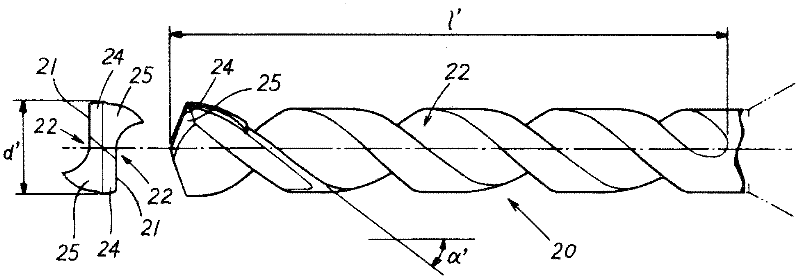
[0055] This embodiment is a drilling tool as follows: one or more cutting edges are provided at the end of the tool main body 1, and a plurality of helical cutting edges are provided on the outer periphery of the tool main body 1 from the end of the tool toward the base end side. Chip removal flutes 2, 3, the plurality of chip removal flutes 2, 3 include one main flute and more than one auxiliary flute, the auxiliary flute 3 is connected to the middle part of the main flute 2, and the The helix angles of the main flute 2 and the sub flute 3 are set to approximately equal angles at the base end side of the tool from the connecting portion 4 where the main flute 2 and the sub flute 3 are connected. The groove length is set to be 50% to 95% of the groove length of the main groove 2, and the auxiliary groove 3 is provided at a predetermined position from the connection setting pa...


PUM


Abstract

Provided is a drilling tool, capable of preventing the cuttings from coiling. Even a drill with a small diameter can have a relatively long anti-damaging lifetime and realize excellent hole-site precision, stable drill processing, and excellent practical applicability. The tail end of the tool body is provided with one or a plurality of cutting edges. The periphery of the tool body is provided with a plurality of helical chip rooms in the direction toward base end side from tail end of the tool. The chip rooms comprise one main groove and more than one auxiliary grooves, wherein the auxiliary grooves are connected with the main groove at the midway section of the main groove. Moreover, the helical angles of the main groove and the auxiliary grooves are designed to have roughly equal angles from the connection setting section set by the connection between the main groove and the auxiliary grooves. The length of the auxiliary grooves is designed to be 50% to 95% of the length of the main groove. Also, the auxiliary grooves are set to be parallel to the main groove within a range from the connection setting section to a predetermined position away from the terminal of the main groove.

Description

technical field [0001] The invention relates to a drilling tool. Background technique [0002] In the drilling process of printed circuit boards (PCB), use such as figure 1 A drill composed of a drill body A having a cutting edge C and a shank B as shown. Depending on the application, the size of the drill varies, but generally speaking, drills with a diameter of 0.7 mm or less are used. [0003] Specifically, on the blade C, such as figure 2 As shown, a helical chip flute 22 is formed on the outer periphery of the main body 20 from the drill tip to the base end side. The cutting edge 21 is formed at the intersecting ridgeline portion (for example, refer to Patent Documents 1 and 2). In addition, in the figure, reference numeral 25 is a second relief surface, and the second relief surface 25 is continuously provided on the rear side of the first relief surface 24 in the tool rotation direction, d' is a tool diameter, and l' is a flute The groove length, α' is the helix...

Claims


Application Information

Patent Timeline
Patent Type & Authority Applications(China)
IPC IPC(8): B23B51/00B23B51/02
CPCB23B2251/24B26F1/16B26F2210/08H05K3/0047
Inventor 风间悠作青野甲子郎安田俊夫星幸义
Owner UNION TOOL
Why Eureka
Try Eureka