
Method for controlling material winding speed

A technology of coiling speed and control method, which is applied in the directions of coiling strips, thin material processing, transportation and packaging, etc., can solve the problems of not being able to adjust the coiling shaft speed in time, material stretching and deformation, and high detection costs, and achieve Improve detection accuracy and calculation speed, improve production efficiency, and avoid stretching deformation

Active Publication Date: 2012-05-30
MESNAC
View PDF5 Cites 6 Cited by
  • Summary
  • Abstract
  • Description
  • Claims
  • Application Information

AI Technical Summary

Problems solved by technology

[0006] In the process of identifying the coiling radius and controlling the rotational speed of the coiling shaft, the coiling radius is a fast time-varying parameter. If the radius change Δr is set to a small value, it is easy to lag in the adjustment of the rotational speed of the coiling shaft. The coiling speed will be fast and slow; if the radius change Δr is set to be large, the speed of the coiling shaft cannot be adjusted in time, and the material will be stretched and deformed easily.
[0007] Moreover, using devices such as ultrasonic sensors to measure the coiling radius has a relatively high detection cost

Method used


Image

  • Method for controlling material winding speed
  • Method for controlling material winding speed

Examples


Embodiment 1

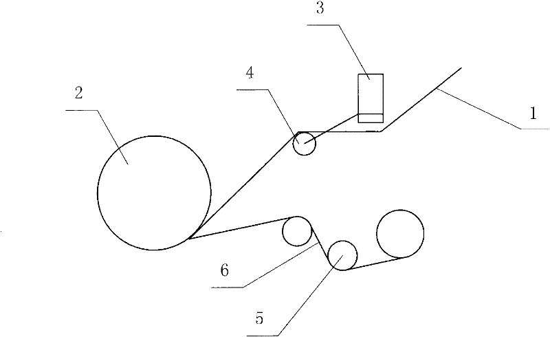
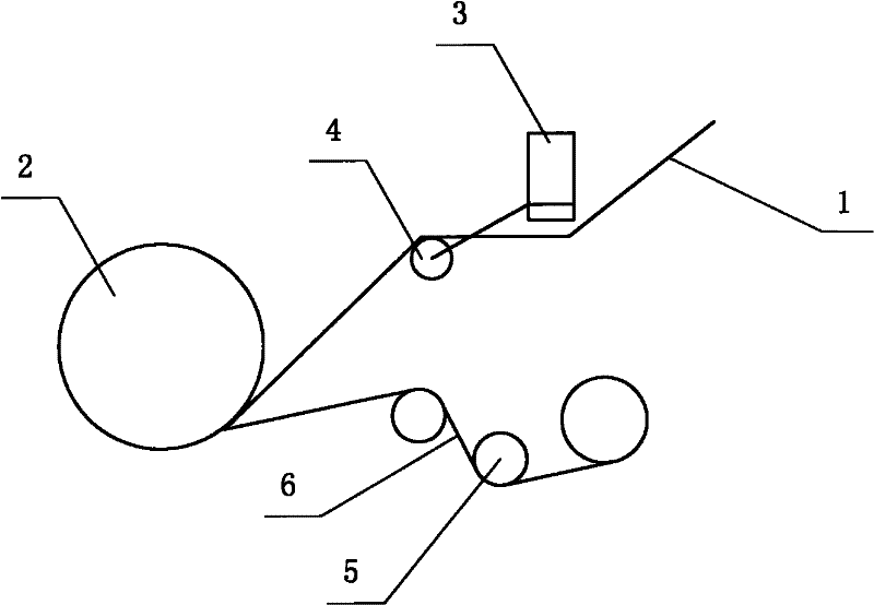
[0042] Example 1, such as figure 1 As shown, the method for controlling the speed of material coiling is applied to the rubber tire manufacturing process, and the blank semi-finished material (such as steel cord, inner liner or belt layer) is transported to the coiling roller 2 through the conveyor belt 1 Complete the coiling with a pad cloth into a roll.

[0043] The floating roller 4 of the speed adjusting device 3 is suspended and supported under the material to dynamically adjust the rotational angular velocity ω of the take-up roller 2 .

[0044] The rotational angular velocity ω of take-up roller 2 conforms to the expression ω=V / C, wherein,

[0045] V is the linear velocity of the conveyor belt 1, and V is set as a constant value;

[0046] C is the circumference of the material when it is coiled on the take-up roller 2, C=2лr, r is the radius of the material coiled, and C is a variable that changes in real time.

[0047] During the material coiling process, an angle s...


PUM


Abstract

The invention provides a method for controlling a material winding speed. Through the method, the material winding circumference is detected so as to exactly adjust a rotation angle speed of a winding roller; the change of rotation speeds of the winding roller is buffered through fluctuation of a floating roller relative to a balance position, so as to realize the match between the winding speed and a transportation line speed, prevent materials from being stretched and deformed, and improve the material winding and storing quality. The control method comprises: the materials are transported to the winding roller through a conveying belt so as to complete the winding with laying cloth; and the floating roller is suspended and supported below the materials so as to adjust the rotation angle speed omega of the winding roller. Compared with the prior art, the rotation angle speed omega of the winding roller in the method provided by the invention satisfies the expression: omega =V / C, wherein V is the linear velocity of the conveying belt; C is the circumference of the material winding on the winding roller; during the winding process, an included angle between the balance position of the floating roller and a horizontal reference line is set as a0; and an angle formed by the fact that the floating roller each additionally rotates a delta a relative to the balance position is detected, namely the material winding circumference is correspondingly increased with a length of delta C.

Description

technical field [0001] The invention relates to a control method for material coiling speed, which belongs to the fields of production automation and rubber machinery. Background technique [0002] According to the existing rubber tire manufacturing and processing technology, all materials that constitute the semi-finished tire embryo need to be bonded and rolled on the forming drum, such as steel cord, inner liner or belt layer, etc. The forming drum is then cut to length. [0003] Usually, the above-mentioned materials are rolled into rolls with the pad cloth on the coiling device. The main function of the coiling device is to coil the continuously produced and transported materials into rolls and store them. The surface of the material is flat, wrinkle-free, and the curling is neat through the coiling with the pad cloth, which is easy to store and transport. In order to prevent the material from being stretched and deformed, it is required to ensure that the curl is mod...

Claims


Application Information

Patent Timeline
IPC IPC(8): B65H23/195
Inventor 张焱王福业李建强孙广东刘朋霞
Owner MESNAC
Learn More