Centralized automatic control system for electric roller

An automatic control system, electric roller technology, applied in the direction of electrical program control, comprehensive factory control, comprehensive factory control, etc., to achieve the effect of solving real-time and meeting the requirements of collaborative control

Inactive Publication Date: 2012-05-30
SHANGHAI MUNICIPAL ELECTRIC POWER CO +2
View PDF6 Cites 4 Cited by
  • Summary
  • Abstract
  • Description
  • Claims
  • Application Information

AI Technical Summary

Problems solved by technology

[0003] The purpose of the present invention is to provide a centralized automatic control system for electric rollers that solves the real-time, rapidity, reliability and voltage matching problems of network control in order to overcome the defects of the above-mentioned prior art

Method used


Image

  • Centralized automatic control system for electric roller
  • Centralized automatic control system for electric roller

Examples


Embodiment

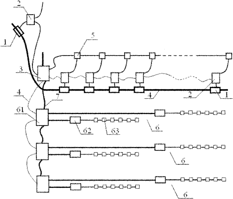
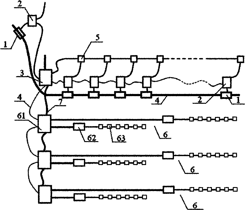
[0020] A centralized automatic control system for electric rollers, its structure is as follows figure 1 As shown, the system includes a conveyor 1, a frequency conversion control box 2, a centralized network control box 3 and a roller control device 6. There are at least 2 conveyors 1, and 14 are provided in this embodiment. Each conveyor 1. Driven by two AC asynchronous motors, one conveyor is set outside the tunnel, and the rest of the conveyors are set inside the tunnel. The conveyors are connected by optical cables 4, and one end of the frequency conversion control box 2 is set with a power tap 5. Each power tap 5 is connected to the network centralized control box 3 via an optical cable. Roller control equipment 6 is provided with three groups, is connected with network centralized control box 3 through optical cable, and roller control equipment 6 comprises wheel control box 61, wheel sub-controller 62 and wheel 63, and wheel control box 61 has optical fiber communicati...


PUM


Abstract

The invention relates to a centralized automatic control system for an electric roller. The system comprises conveyors, variable-frequency speed regulation control boxes, a network centralized control box and a roller control device, wherein one conveyor is arranged outside a tunnel, the rest conveyers are all arranged in the tunnel, and all the conveyers are mutually connected via optical cables; and the variable-frequency speed regulation control boxes are connected with the conveyors via electric cables and connected with the network centralized control box via optical cables. Compared with the prior art, the system provided by the invention has the advantages that the voltage matching problem is effectively solved, a photoelectric converter is adopted to realize signal transmission based on optical fiber communication, the network control is realized quickly and reliably in real time, and the requirement on cooperative control for power cable laying is satisfied.

Description

technical field [0001] The invention relates to an electric power control system, in particular to a centralized automatic control system for electric rollers. Background technique [0002] The power cable laying network control system includes three parts, which are carried out in sequence according to the actual cable laying project requirements and time progress. The hybrid laying method of conveyors and electric rollers is adopted to meet the laying requirements of large cross-section and long-distance 500kV EHV cables. The existing conveyor frequency conversion centralized automatic control system completes the operation through the conveyor, each conveyor is driven by two AC asynchronous motors, and the speed control scheme adopts frequency conversion drive. The automatic control structure of Profibus field bus is formed by optical fiber communication technology. Each frequency conversion speed control box can be independently controlled to realize the local independ...

Claims


Application Information

Patent Timeline
Patent Type & Authority Applications(China)
IPC IPC(8): G05B19/418
CPCY02P90/02
Inventor 张永隆姜芸曹以龙闵红马骏
Owner SHANGHAI MUNICIPAL ELECTRIC POWER CO
Why Eureka
Try Eureka