Nonaqueous electrolyte battery

A non-aqueous electrolyte and battery technology, applied in the manufacture of non-aqueous electrolyte batteries, electrodes of non-aqueous electrolyte batteries, electrolyte batteries, etc., can solve problems such as current collector deformation, separator damage, etc. sexual effect

Active Publication Date: 2012-05-30
MURATA MFG CO LTD
View PDF9 Cites 11 Cited by
  • Summary
  • Abstract
  • Description
  • Claims
  • Application Information

AI Technical Summary

Problems solved by technology

Therefore, the end of the electrode lead can easily cause damage to the separator
This problem is more prone to occur in electrode device configurations where the electrode leads are located between the facing planes of the positive and negative electrodes
[0006] In addition, in the case of wound-type battery devices, where the

Method used


Image

  • Nonaqueous electrolyte battery
  • Nonaqueous electrolyte battery
  • Nonaqueous electrolyte battery

Examples


no. 1 example

[0032]1. First embodiment (example in which the position of the end of the electrode lead is adjusted and the edge of the electrode lead is processed)

[0033] 2. Second embodiment (example where electrode lead end is coated)

no. 3 example

[0034] 3. Third Embodiment (Example Using Another Electrode Lead Connection Method)

[0035] 1. The first embodiment

[0036] 1-1. Overall structure of non-aqueous electrolyte battery

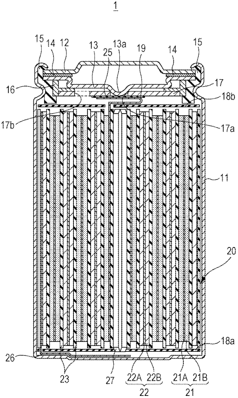
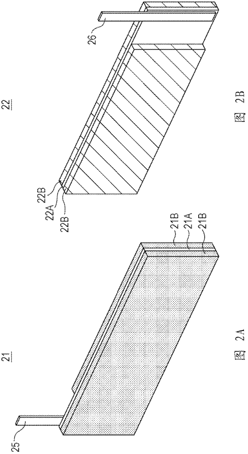
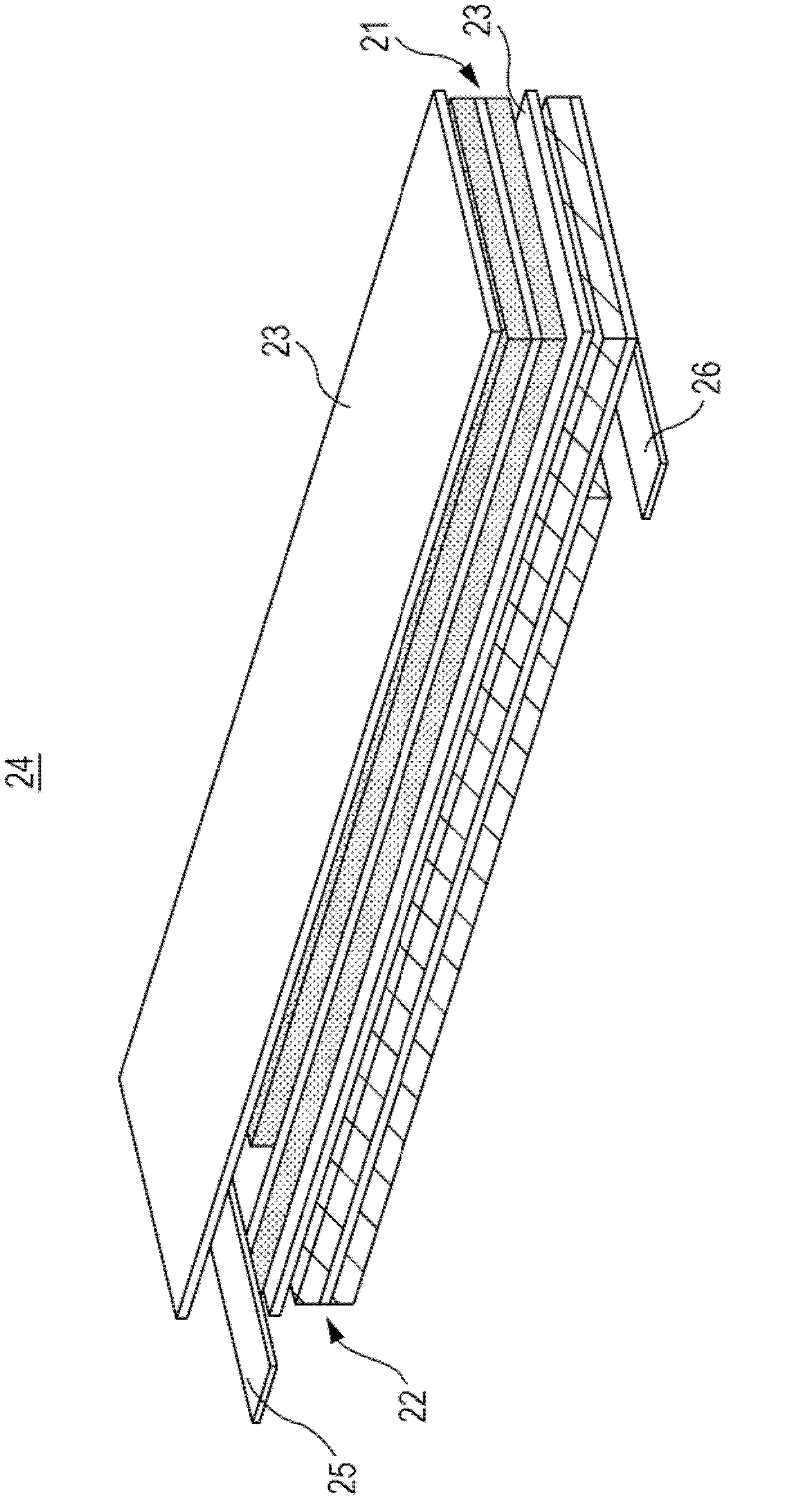
[0037] figure 1 A sectional view of a lithium ion secondary battery is shown, which is an example of the nonaqueous electrolyte battery 1 according to an embodiment of the present disclosure. The battery has a cylindrical shape and includes a wound electrode body 20 formed by winding a strip-shaped positive electrode 21 and a strip-shaped negative electrode 22 within an approximately hollow cylindrical battery case 11, Wherein the separator 23 is sandwiched between the positive electrode 21 and the negative electrode 22 together with a non-aqueous electrolyte solution (not shown). The battery case 11 is formed of, for example, nickel-plated steel, and one end of the battery case 11 is closed and the other end is opened. Inside the battery case 11, a pair of insulating plates 18a and 18b per...

no. 4 example

[0142] In this fourth embodiment, a nonaqueous electrolyte battery using a laminate in which a positive electrode and a negative electrode are laminated will be described.

[0143] 4-1. Structure of non-aqueous electrolyte battery

[0144] Figure 11A A perspective view showing the appearance of the nonaqueous electrolyte battery 30 according to the fourth embodiment is shown, Figure 11B An exploded perspective view showing the configuration of the nonaqueous electrolyte battery 30 . in addition, Figure 11C A perspective view showing the structure of the lower surface of the non-aqueous electrolyte battery 30, Figure 11D showing along Figure 11A Sectional view taken at midline XID-XID. In addition, in the following description, in the non-aqueous electrolyte battery 30, the part from which the positive electrode lead 32 and the negative electrode lead 33 protrude is called the top, and the part opposite to the top is called the bottom, between the top and the bottom. ...


PUM

PropertyMeasurementUnit
Thicknessaaaaaaaaaa
Thicknessaaaaaaaaaa
Thicknessaaaaaaaaaa

Abstract

There is provided a nonaqueous electrolyte battery including a first electrode having a strip shape, a second electrode having a strip shape, a first electrode lead, a second electrode lead, a separator having a strip shape that is disposed between the first electrode and the second electrode, and a nonaqueous electrolyte. A laminated electrode body, which is obtained by laminating the first electrode and the second electrode through the separator in such a manner that the second electrode lead is disposed at the other end portion of the second electrode not opposite to one end portion of the first electrode to which the first electrode lead is connected, is wound in a longitudinal direction with one end to which the first electrode lead is connected made as an initial end, and a wound electrode body is obtained.

Description

Background technique [0001] The present disclosure relates to a nonaqueous electrolyte battery, in particular, to a nonaqueous electrolyte battery in which an electrode lead for drawing current is connected to a positive electrode and a negative electrode. [0002] In recent years, portable electronic devices such as camera-integrated VTRs (Video Recorders), cellular phones, and notebook PCs have been widely used, and attempts have been made to reduce the weight of such devices. In order to increase the energy density as a key device, batteries, especially secondary batteries, as portable power sources of such electronic devices are being actively developed. In these batteries, compared with lead batteries and nickel-cadmium batteries which are aqueous electrolyte solution secondary batteries in the related art, a large energy density can be obtained in non-aqueous electrolyte batteries such as lithium-ion batteries, so people are working in various fields. In the face of the...

Claims


Application Information

Patent Timeline
IPC IPC(8): H01M2/26H01M4/13H01M10/058H01M50/533H01M50/534H01M50/553H01M50/559
CPCH01M2/30H01M4/70H01M10/0431H01M10/0583Y02E60/122H01M2/26H01M10/052H01M10/0459H01M10/0587Y02E60/10Y02P70/50H01M50/553H01M50/534H01M50/559H01M50/533
Inventor 岩间正之川瀬贤一高田智雄
Owner MURATA MFG CO LTD
Why Eureka
Try Eureka