Piston engine having magnetic piston bearing

A piston engine and piston technology, applied in free piston engines, bearings, magnetic bearings, etc., can solve the problems of high maintenance costs and high environmental load, and achieve the effects of preventing friction, economical production, and convenient production.

Inactive Publication Date: 2012-05-30
SIEMENS AG
View PDF3 Cites 4 Cited by
  • Summary
  • Abstract
  • Description
  • Claims
  • Application Information

AI Technical Summary

Problems solved by technology

In internal combustion engines, parts of the lubricating oil are always combusted together and this leads especially to a high environmental burden.
The lubricating oil is destroyed

Method used


Image

  • Piston engine having magnetic piston bearing
  • Piston engine having magnetic piston bearing
  • Piston engine having magnetic piston bearing

Examples


Embodiment Construction

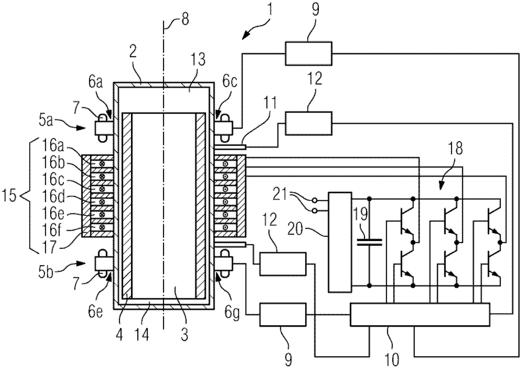
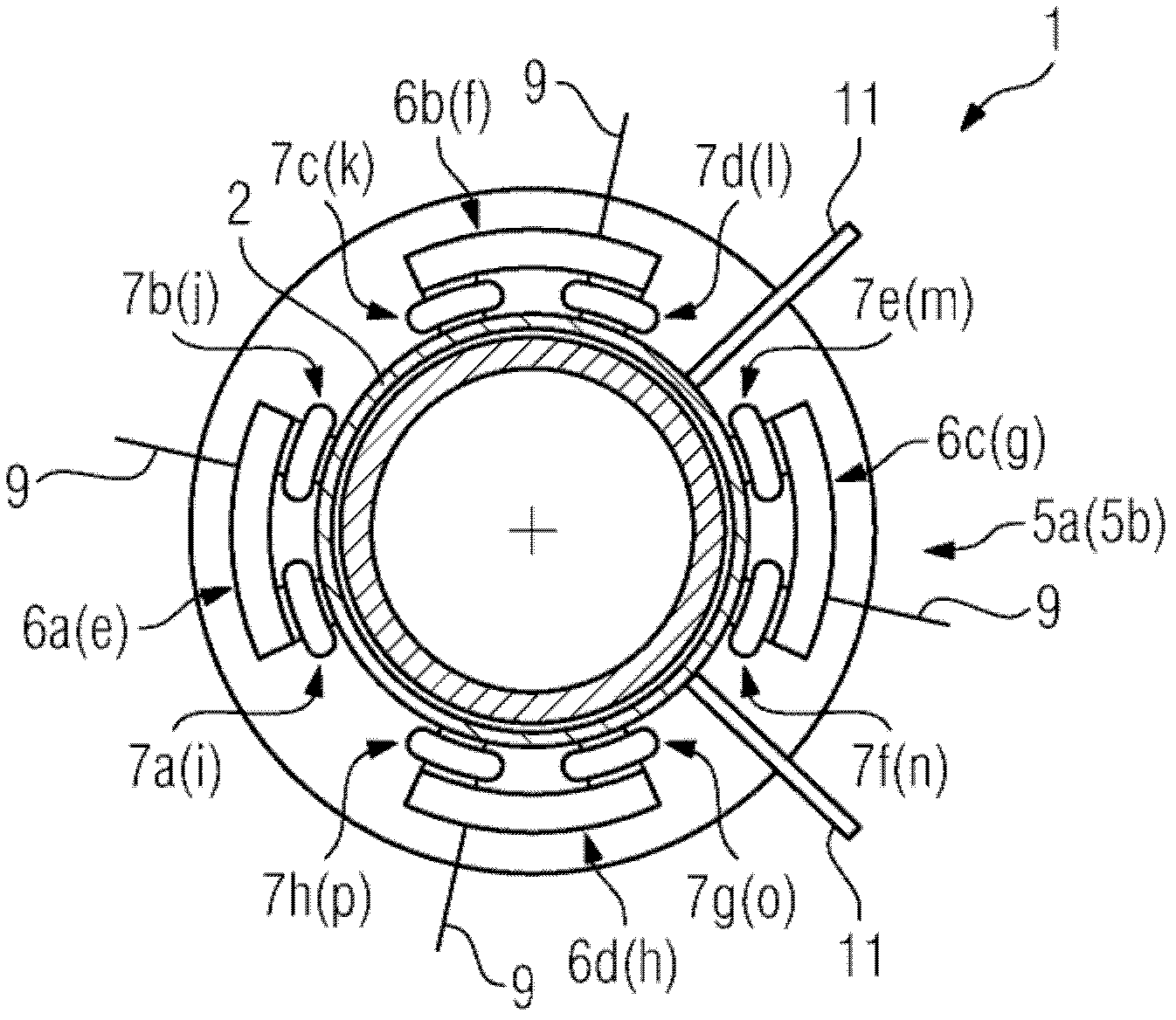
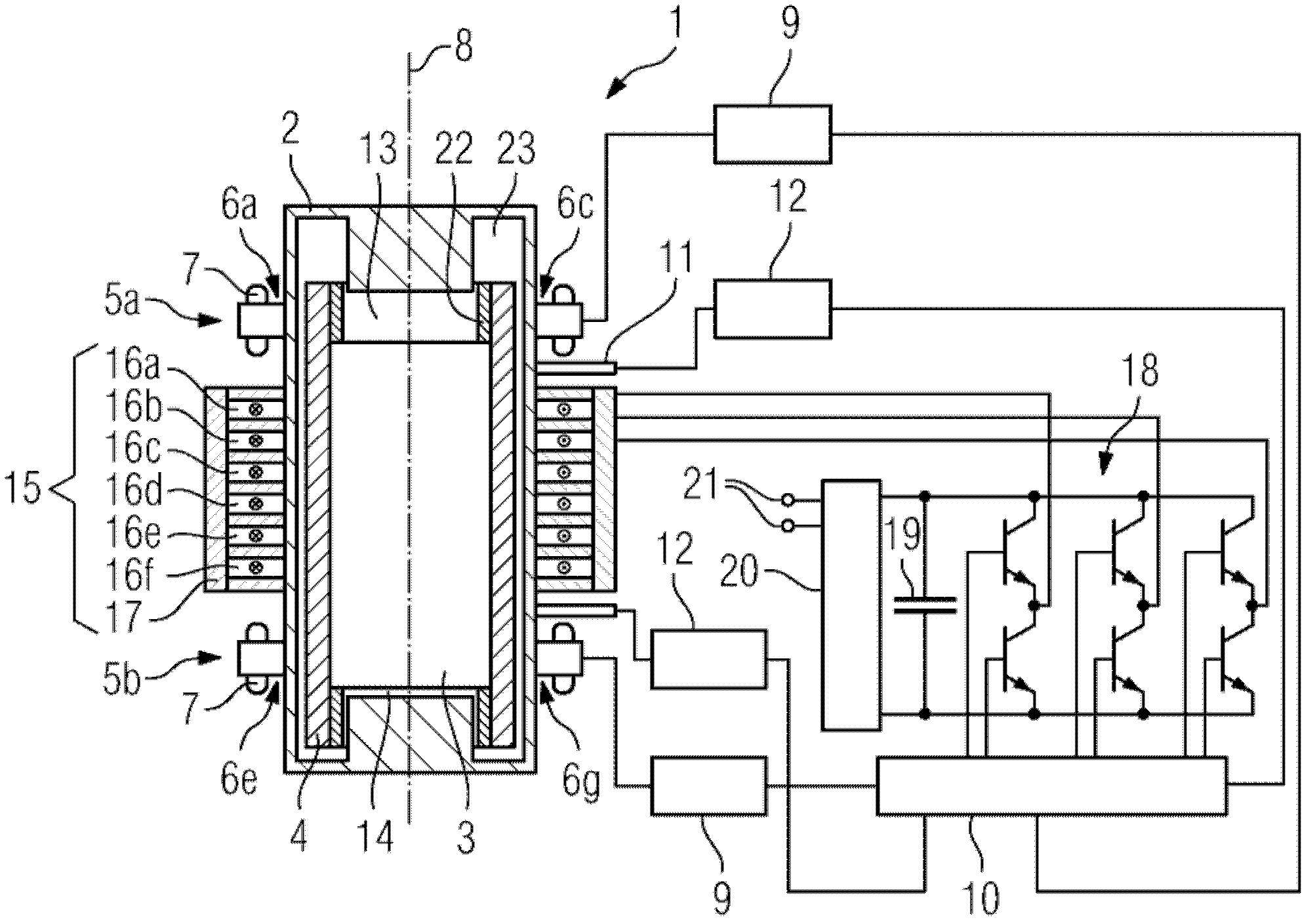
[0033] figure 1 A section of a piston machine 1 according to the invention is shown. The piston machine 1 has a cylindrical housing 2 in which a cylindrical piston 3 is movably mounted. A yoke 4 is provided on the outer peripheral surface of the cylindrical piston 3 . On the outside of the housing 2, at two positions 5a and 5b of its cylindrical outer circumference, at four support points 6a to 6d or 6e to 6g along the outer circumference, two magnets for magnetically supporting the piston 3 are respectively provided. Roads 7a to 7p. According to another embodiment not shown in the figure, there are three supporting points 6a to 6c, which each have a magnetic circuit 7a to 7f, which may be sufficient for a stable mounting of the piston. Combining the above numbers or depending on the use and force, the number of magnetic circuits can be changed according to the desired application. For simplicity, in figure 1 In the sectional view of , each position 5a and 5b only shows t...


PUM


Abstract

The present invention relates to a piston engine (1). Said engine comprises a housing (2) and a piston (3). The piston (3) is magnetically and movably disposed in the housing (2). A device (7) for magnetically supporting the piston (3) is fixedly mounted relative to the housing (2). A linear machine (15) in conjunction with the magnetic bearing of the piston (3) can prevent friction and thus result in a machine for converting mechanical into electric energy without having to lubricate and with reduced mechanical effort.

Description

technical field [0001] The invention relates to a piston machine comprising at least one first piston and at least one first housing. The at least one first housing completely or at least partially surrounds the at least one first piston. The at least one first piston is movably magnetically supported in the at least one first housing by means of at least one device for magnetically supporting the at least one first piston. Background technique [0002] Heat engines are used to convert chemical energy to mechanical energy, thermal energy to mechanical energy, and mechanical energy to thermal energy. An internal combustion engine as a heat engine converts chemical energy into mechanical energy, a Stirling engine as a heat engine converts thermal energy into mechanical energy, and a heat pump as a heat engine converts mechanical energy into thermal energy. One of the most frequently used heat engines is the piston machine, in which the mechanical energy of the piston is tran...

Claims


Application Information

Patent Timeline
IPC IPC(8): F02B71/00F16C29/00F16C32/04
CPCF16C32/0472F16C32/048F02B71/00F16C29/00F16C32/04F02B63/04F02B63/044F02B75/16F02B77/13
Inventor M.克洛普齐格
Owner SIEMENS AG
Why Eureka
Try Eureka