Laser projector

一种激光投影仪、激光的技术,应用在激光投影仪领域,能够解决波长、入射角度限制、功率集中、未充分研究激光投影仪等问题,达到高安全性的效果

Inactive Publication Date: 2012-05-30
PANASONIC CORP
View PDF10 Cites 30 Cited by
  • Summary
  • Abstract
  • Description
  • Claims
  • Application Information

AI Technical Summary

Problems solved by technology

However, if these elements are used as beam shaping means, the wavelength and incident angle to be used are limited.
Therefore, the utilization of these elements as beam shaping means is not suitable for homogenization or correct beam shaping of light intensity for most wavelengths or multiple light sources
Furthermore, as a result of the use of these elements as beam shaping members, it is easy to generate sites of power concentration due to zero-order light
[0014] The above-mentioned conventional proposals have not sufficiently studied the optical design for realizing the reduction of speckle noise, high brightness, and high safety while maintaining the miniaturization of laser projectors

Method used


Image

  • Laser projector
  • Laser projector
  • Laser projector

Examples


no. 1 approach

[0041] (laser projector)

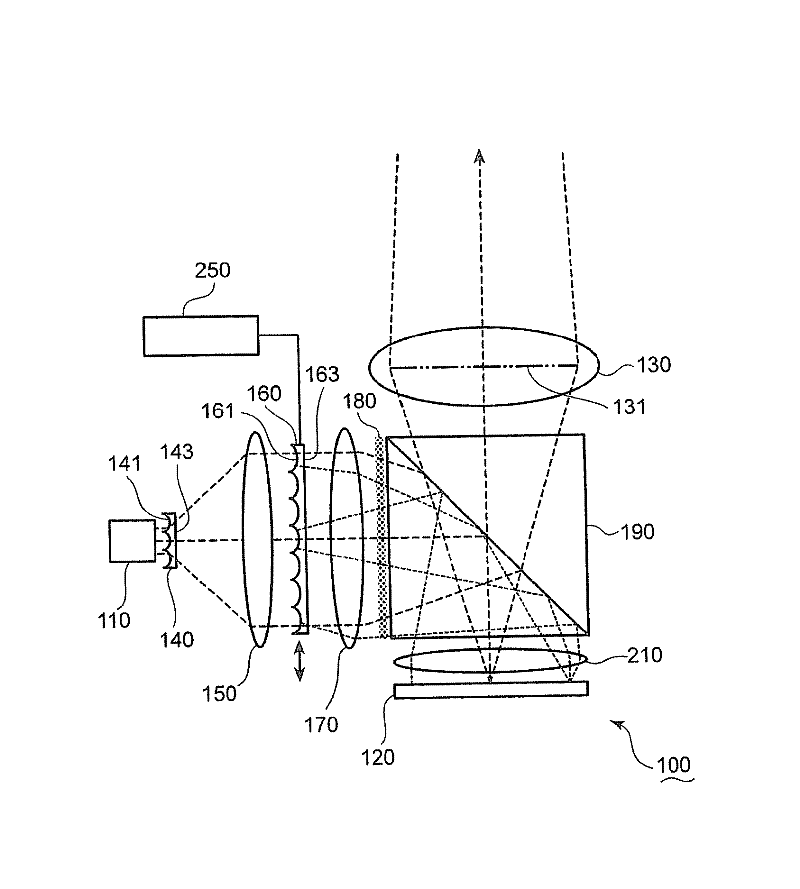
[0042] figure 1 is a schematic diagram of the laser projector 100 according to the first embodiment. use figure 1 The laser projector 100 will be described.

[0043] The laser projector 100 includes a laser light source 110 for emitting laser light, a spatial light modulator 120 for modulating the laser light to generate image light, and a projection lens 130 for emitting image light. In this embodiment, the laser light source 110 is exemplified as a laser light source unit.

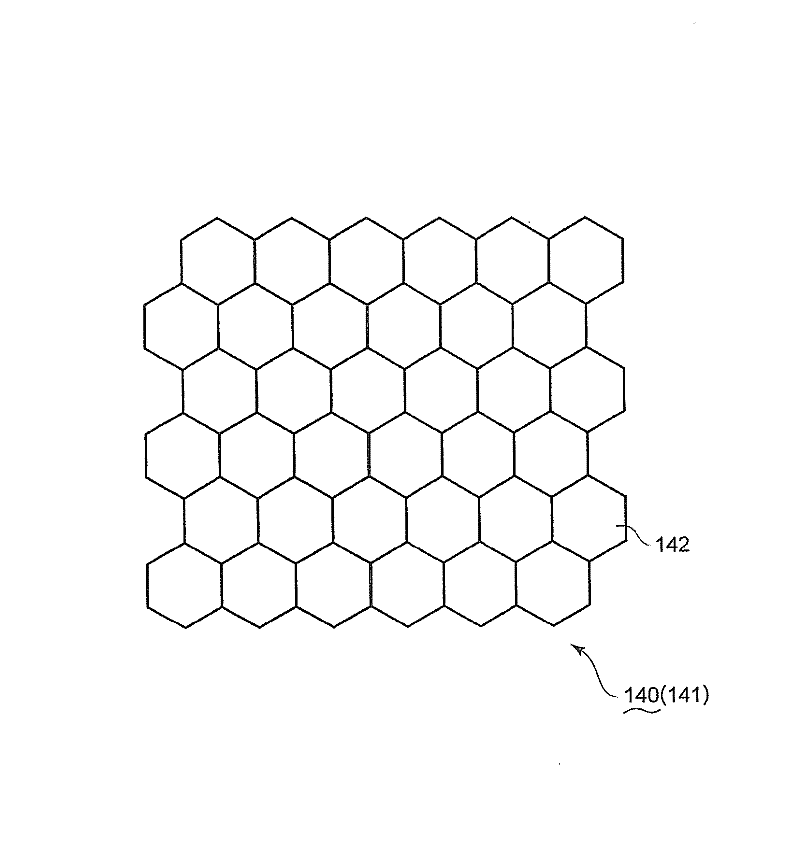
[0044] figure 1 In , an exit pupil (exit pupil) 131 of the projection lens 130 is indicated by a thick dotted line. The laser projector 100 further includes a pupil homogenizing element 140 that homogenizes the light intensity distribution of the exit pupil 131 of the projection lens 130 . The pupil uniformizing element 140 has an incident end surface 141 on which laser light from the laser light source 110 enters.

[0045] figure 2 is a schematic diagram of a lens pat...

no. 2 approach

[0115] Figure 7 It is a schematic diagram of a laser projector 100A according to the second embodiment. use Figure 7 The laser projector 100A will be described. In addition, the same code|symbol is attached|subjected to the same element as the element demonstrated in 1st Embodiment. Descriptions of these same elements are omitted.

[0116] Like the laser projector 100 of the first embodiment, the laser projector 100A includes a pupil uniformizing element 140, a collimator 150, a condenser lens 170, a light diffusing element 180, a PBS 190, a field lens 210, a projection lens 130, and an actuator. device 250. The laser projector 100A further includes a red laser light source 110r emitting red laser light, a green laser light source 110g emitting green laser light, and a blue laser light source 110b emitting blue laser light. In this embodiment, the red laser light source 110r, the green laser light source 110g, and the blue laser light source 110b are exemplified as lase...

no. 3 approach

[0134] Figure 8 It is a schematic diagram of a laser projector 100B according to the third embodiment. use figure 2 as well as Figure 8 The laser projector 100B will be described. In addition, the same code|symbol is attached|subjected to the same element as the element demonstrated in 1st Embodiment and 2nd Embodiment. Descriptions of these same elements are omitted.

[0135] Like the laser projector 100 of the first embodiment, the laser projector 100B includes a pupil uniformizing element 140 , a collimator 150 , and an actuator 250 . In addition, the laser projector 100B further includes a red laser light source 110r, a green laser light source 110g, a blue laser light source 110b, a collimator 111, and a multiplexer prism 112 similarly to the laser projector 100A of the second embodiment.

[0136] The laser projector 100B further includes a spatial light modulation element 120B that modulates laser light to generate image light. In this embodiment, a DMD (Digital...


PUM


Abstract

A laser projector is characterized by being provided with a laser beam source unit (110) for emitting a laser beam, a spatial beam modulation element (120) for modulating the laser beam and generating image light, a projection lens (130) for emitting the image light, a beam shaping element (160) for forming the beam shape of the laser beam into the shape of the spatial beam modulation element (120), and a pupil homogenization element (140) for homogenizing the light intensity distribution of an exit pupil (131) of the projection lens, the pupil homogenization element (140) being disposed between the laser beam source unit (110) and the beam shaping element (160).

Description

technical field [0001] The present invention relates to a laser projector using laser light as a light source. Background technique [0002] In recent years, projectors that project images on various projection surfaces such as screens have become popular. Projectors generally use bulb light sources. However, bulb light sources have a short lifespan. In addition, the color reproduction area of ​​bulb light sources is limited. In addition, the bulb light source has disadvantages such as large light source area and low light utilization efficiency. [0003] In order to solve these problems, try to use a laser light source as the light source of the projector. Compared with the bulb light source, the laser light source has a longer life and stronger directivity. Therefore, the laser light source can easily achieve high light utilization efficiency. In addition, the laser light source is monochromatic, enabling a large color reproduction area. Therefore, projectors utiliz...

Claims


Application Information

Patent Timeline
Patent Type & Authority Applications(China)
IPC IPC(8): G03B21/14G02B27/18H04N5/74
CPCG02B27/48H04N9/3161G03B21/2033G02B27/141G02B27/0933H04N9/3164G02B13/007G03B21/2006G03B21/14G03B21/208
Inventor 水岛哲郎伊藤达男笠澄研一中山健二
Owner PANASONIC CORP
Why Eureka
Try Eureka