Sealer for capacitor and aluminum electrolytic capacitor using same
A sealing body and capacitor technology, which is applied in the direction of capacitor shell/packaging, capacitor parts, etc., can solve the problem of inability to reduce electrolyte evapotranspiration, and achieve the effect of inhibiting evapotranspiration
- Summary
- Abstract
- Description
- Claims
- Application Information
AI Technical Summary
Problems solved by technology
Method used
Image
Examples
Embodiment approach 1
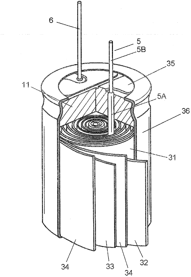
[0040] figure 1 It is a perspective view of the aluminum electrolytic capacitor in Embodiment 1 of this invention. The capacitor element 31 is constituted by winding the anode foil 32 and the cathode foil 33 formed of aluminum foil with a separator 34 interposed therebetween. The lead wire 5 is bonded to the anode foil 32 . The lead wire 5 has a joining portion 5A to which the anode foil 32 is joined, and a solderable external lead portion 5B. The lead wire 6 is bonded to the cathode foil 33 . The lead 6 also has a bonding portion and an external lead-out portion in the same manner.
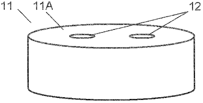
[0041] The capacitor element 31 is impregnated with an electrolytic solution (not shown), and is accommodated in a bottomed cylindrical case 35 made of aluminum. The opening of the case 35 is sealed by the sealing body 11 . The outer periphery of the case 35 is covered by the exterior member 36 .
[0042] The electrolyte is prepared by dissolving an electrolyte salt in a solvent. The solve...
Embodiment 1~12
[0083] Materials constituting the sealing bodies of Examples 1 to 12 of the present embodiment are shown below. In addition, the composition (parts by weight) of each Example is shown in (Table 1).
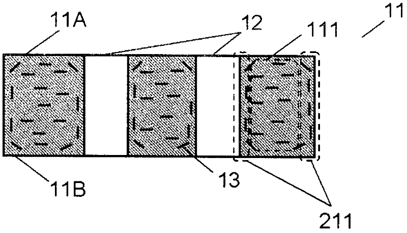
[0084] Butyl rubber (268 manufactured by JSR) was used as a polymer, and an alkylphenol formaldehyde resin was used as a crosslinking agent. Five kinds of natural mica were used as the flat inorganic substance 13 as shown below. The average particle size of mica A was 20 μm, and the aspect ratio was 0.567. The average particle size of mica B was 23 μm, and the aspect ratio was 0.577. The average particle size of mica C was 25 μm, and the aspect ratio was 0.584. The average particle size of mica D was 30 μm, and the aspect ratio was 0.602. The average particle size of mica E was 50 μm, and the aspect ratio was 0.672. Silicone oil-treated silica (polysulfide manufactured by Daiso) or silane-coupling-treated clay (vinylsilane manufactured by BASF) was used as the inorganic fille...
Embodiment approach 2
[0098] 5A to 5C It is a schematic diagram which shows the procedure of press molding of the sealing body 11 in Embodiment 2 of this invention. The basic structure of the aluminum electrolytic capacitor of the present embodiment is the same as that of the first embodiment except for the sealing body 11 . In this embodiment, instead of the sheet 14 in the first embodiment, a sheet 20 obtained by laminating two types of sheets 20A and 20B having different contents of the flat inorganic substance 13 is used. As a result, the distribution of the flat inorganic substances 13 in the sealing body 11 is different. Otherwise, it is the same as that of Embodiment 1.
[0099] Below, refer to 5A to 5C The manufacturing method of the molded object 18B which is the precursor of the sealing body 11 of this embodiment is demonstrated. First, as Figure 5A As shown, using the lower die 16 in which two pins 16A were erected on the bottom surface of the cylindrical recess, and the upper di...
PUM
 Abstract
Description
Claims
Application Information
 - R&D
- Intellectual Property
- Life Sciences
- Materials
- Tech Scout
- Unparalleled Data Quality
- Higher Quality Content
- 60% Fewer Hallucinations
Browse by: Latest US Patents, China's latest patents, Technical Efficacy Thesaurus, Application Domain, Technology Topic, Popular Technical Reports.
© 2025 PatSnap. All rights reserved.Legal|Privacy policy|Modern Slavery Act Transparency Statement|Sitemap|About US| Contact US: help@patsnap.com


