
Electric drill capable of achieving protection function diversification

A protection function, electric drill technology, applied in the field of electric drills with diversified protection functions, can solve the problems of dust particles splashing, uneven hole depth, drill bit stuck in the object to be drilled, etc., to improve the safety factor, maintain consistency, The effect of protecting eyes

Active Publication Date: 2020-04-17
浙江意达电器有限公司
View PDF12 Cites 2 Cited by
  • Summary
  • Abstract
  • Description
  • Claims
  • Application Information

AI Technical Summary

Problems solved by technology

[0007] When installing the drill bit, the end of the drill bit is usually inserted into the mounting seat and clamped. In the process of starting the electric drill to rotate the drill bit at high speed, once the drill bit is loose from the mounting seat, the high-speed rotating drill bit may hurt workers, so it has the advantages of It is a great unsafe factor, and when drilling on a flat surface, once the drill bit is loosened from the mounting seat, the drill bit may be stuck in the drilled object and is not easy to pull out. Secondly, dust particles are prone to splash during the drilling process. When the dust particles are large, especially when drilling a hole on a wooden board, the sawdust splash may enter the worker's eyes, and at this time the drill bit is in a state of high-speed rotation, and the worker's accidental touch will cause great harm. In addition, The existing electric drill is not convenient to determine the maximum depth of the hole in advance, and in some cases where the drilling depth is required to be consistent, there may be a problem of uneven hole depth

Method used


Image

  • Electric drill capable of achieving protection function diversification
  • Electric drill capable of achieving protection function diversification
  • Electric drill capable of achieving protection function diversification

Examples


Embodiment 1

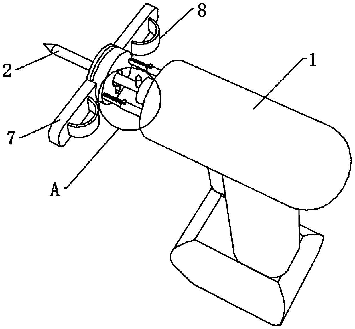
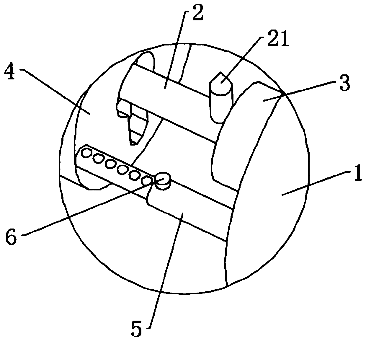
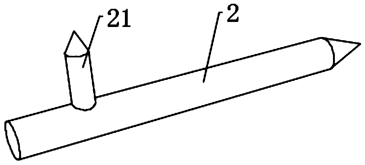
[0047] see Figure 1-5 , an electric drill with diversified protective functions, comprising an electric drill body 1, a mounting seat 3 is movably connected to the electric drill body 1, a drill bit 2 is inserted in the mounting seat 3, and an anti-off rod 21 is fixedly connected to the outer end of the drill bit 2, and The anti-off bar 21 is positioned at the side close to the mounting base 3, and the side of the anti-off bar 21 away from the mounting base 3 is provided with an outer shell 4, the outer shell 4 is made of a transparent material, and the outer shell 4 is dug to match the drill bit 2. The central circular hole 41 and the bar-shaped hole 42 matched with the anti-off rod 21, the length of the anti-off rod 21 is greater than the radius of the central circular hole 41, and the drill bit 2 is inserted in the central circular hole 41, the outer casing 4 and the electric drill An adjusting rod body 5 is fixedly connected between the body 1 , a stud 6 is connected to t...


PUM


Abstract

The invention discloses an electric drill capable of achieving protection function diversification, and belongs to the field of electric drills. The electric drill capable of achieving protection function diversification comprises an electric drill body, an installing base is movably connected to the electric drill body, a drill bit is inserted into the installing base, an anti-separation rod is fixedly connected to the outer end of the drill bit and located on the side close to the installing base, the side, far away from the installing base, of the anti-separation rod is provided with a shell body, the shell body is provided with a central round hole matched with the drill bit and a strip-shaped hole matched with the anti-separation rod, and the drill bit is inserted into the central round hole. Through the structures such as the anti-separation rod, the shell body and an adjusting rod body, the drill bit is not prone to flying out to hurt a worker, and the jammed drill bit can be conveniently pulled out; meanwhile, splashing of dust particles can be effectively blocked, the eyes of the worker are protected, and then the drilling security coefficient is improved; and in addition,the maximum hole depth can be determined in advance, and the consistency of the depths of multiple holes can be effectively kept.

Description

technical field [0001] The invention relates to the field of electric drills, and more specifically relates to an electric drill with diversified protection functions. Background technique [0002] Electric drill is a tool commonly used in machinery industry, construction industry and decoration industry for drilling, screwing and screwing. The working principle of the electric drill is that the motor rotor of the electromagnetic rotary or electromagnetic reciprocating small-capacity motor performs magnetic field cutting and works, drives the working device through the transmission mechanism, and drives the gear to increase the power of the drill bit, so that the drill bit scrapes the surface of the object and penetrates the object better. . [0003] Electric drills can be divided into 3 categories: hand drills, impact drills, and hammer drills. [0004] 1. Electric hand drill: The power is the smallest, and the scope of use is limited to drilling wood and as an electric s...

Claims


Application Information

Patent Timeline
Patent Type & Authority Applications(China)
IPC IPC(8): B23B45/02B23B45/00B23B47/00
CPCB23B45/00B23B45/003B23B45/02B23B47/00
Inventor 丁柳朋
Owner 浙江意达电器有限公司
Learn More