Switching Device For An X-Ray Generator

A switching device, x-ray technology, applied in output power conversion devices, electrical components and other directions, can solve the problems of parasitic inductance, high loss in safe operation of resonant inverter, etc., to reduce switching loss, realize output voltage, reduce The effect of parasitic oscillations

Inactive Publication Date: 2012-05-30
KONINK PHILIPS ELECTRONICS NV
View PDF7 Cites 1 Cited by
  • Summary
  • Abstract
  • Description
  • Claims
  • Application Information

AI Technical Summary

Problems solved by technology

In addition, there may be parasitic inductance
The generated parasitic oscillations can generate high losses that limit the safe operation of the resonant inverter

Method used


Image

  • Switching Device For An X-Ray Generator
  • Switching Device For An X-Ray Generator
  • Switching Device For An X-Ray Generator

Examples


Embodiment Construction

[0042] It should be noted that in the following, the described exemplary embodiments of the invention also apply to methods and devices.

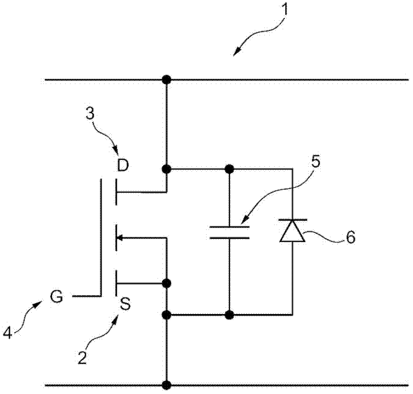
[0043] figure 1 Circuit 1 of MOSFETs including parasitic elements is shown. The MOSFET is an n-type MOSFET including a source 2 , a drain 3 and a gate 4 . There is a parasitic capacitance 5 between the source 3 and the drain 3 . This parasitic or internal capacitance 5 may also be called "coss capacitance". The MOSFET's parasitic capacitance or internal capacitance5 can make the MOSFET's output capacitance. Furthermore, there is a diode 6 in parallel with the parasitic capacitance 5 , which conducts in the direction from the source 2 to the drain 3 and blocks the current in the direction from the drain 3 to the source 2 . figure 1 The circuit 1 of FIG. 1 schematically shows the terminals 2, 3, 4 of the MOSFET, and also shows the internal parasitic elements 5, 6 of the MOSFET.

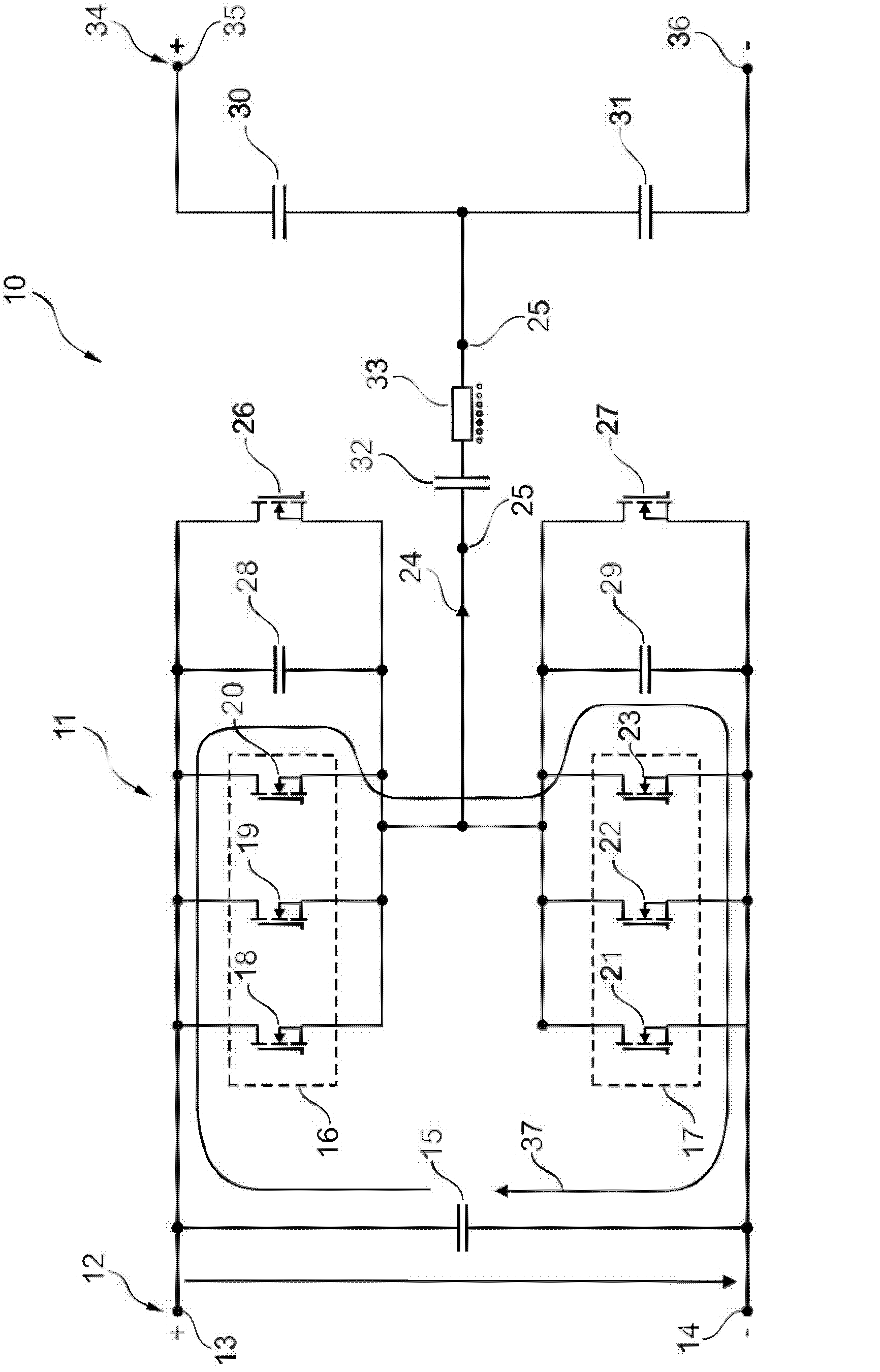
[0044] figure 2 A resonant converter 10 comprising a switc...


PUM


Abstract

The invention relates to a switching device for an X-ray generator for providing a required output power voltage at an output of a resonance power converter. The switching device may comprise a main switch 16 and an auxiliary switch 26, wherein the main switch 16 may comprise a first internal capacitance 5 and wherein the auxiliary switch 26 may be connected in parallel to the main switch 16. Moreover, the main switch 16 may be controllable and the auxiliary switch 26 may be also controllable. Furthermore, the auxiliary switch 26 may be controllable in dependence of the main switch 16, wherein the auxiliary switch 26 may be controllable for discharging of the first internal capacitance 5 of the main switch 16.

Description

Background technique [0001] Radiation generators, especially x-ray generators, may comprise resonant inverters which may operate at high switching frequencies, for example at 100 kHz (kilohertz) or higher. These switching frequencies may result in increased switching losses. [0002] In a resonant inverter, multiple switches may be utilized, eg several MOSFETs. These MOSFETs can be connected in parallel with each other, and their parasitic output capacitance can add up due to the parallel connection. Parasitic output capacitance can be inversely proportional to the generator's mains voltage, and its output capacitance can be especially large at zero voltage switching (ZVS). [0003] The disadvantage is that at turn-on, parasitic oscillations may occur between the drain of the MOSFET and the gate of the MOSFET. These parasitic oscillations may occur between one MOSFET in one part of the circuit bridge and another MOSFET in another part of the circuit bridge. In addition, pa...

Claims


Application Information

Patent Timeline
Patent Type & Authority Applications(China)
IPC IPC(8): H02M1/34
CPCH02M1/34
Inventor N·艾德莱
Owner KONINK PHILIPS ELECTRONICS NV
Why Eureka
Try Eureka