Composite test apparatus of high-voltage direct current transmission converter valve

A high-voltage direct current transmission and synthetic test technology, which is applied in the direction of measuring devices, circuit breaker testing, and measuring electricity, can solve problems such as unsatisfactory equivalence, and achieve the effect of large selection, flexible methods, and wide application range

Active Publication Date: 2012-06-06
CHINA ELECTRIC POWER RES INST +1
View PDF5 Cites 12 Cited by
  • Summary
  • Abstract
  • Description
  • Claims
  • Application Information

AI Technical Summary

Problems solved by technology

However, the high-voltage sources of several sets of synthetic test circuits in the world are composed of oscillating circuits, and their notable feature is that the high voltage provided is positive and negative symm

Method used


Image

  • Composite test apparatus of high-voltage direct current transmission converter valve
  • Composite test apparatus of high-voltage direct current transmission converter valve
  • Composite test apparatus of high-voltage direct current transmission converter valve

Examples


Embodiment 1

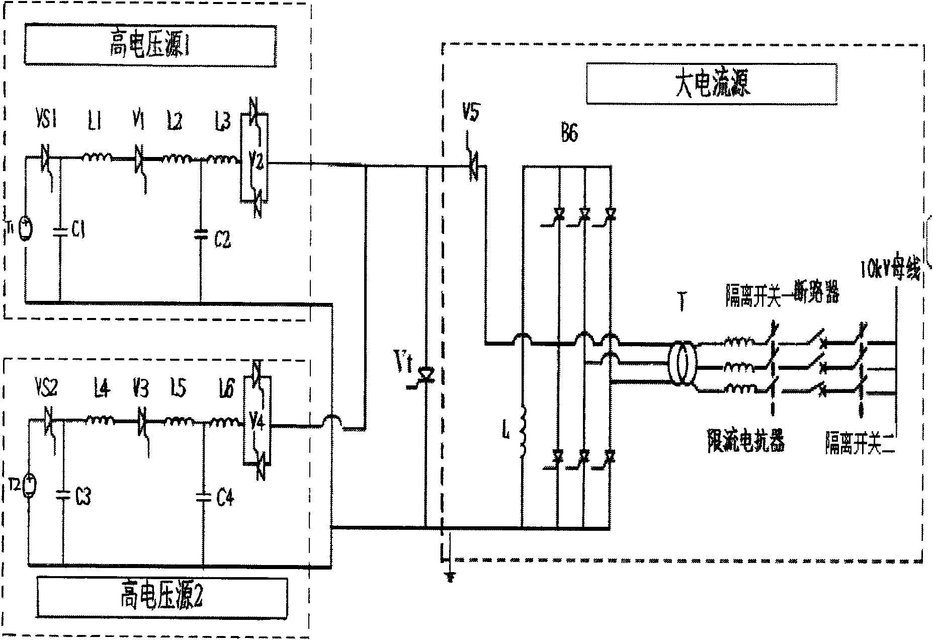
[0024] In the synthesis test of the high-voltage direct current transmission converter valve, the basic working principle of the present invention under the double-injection working mode:

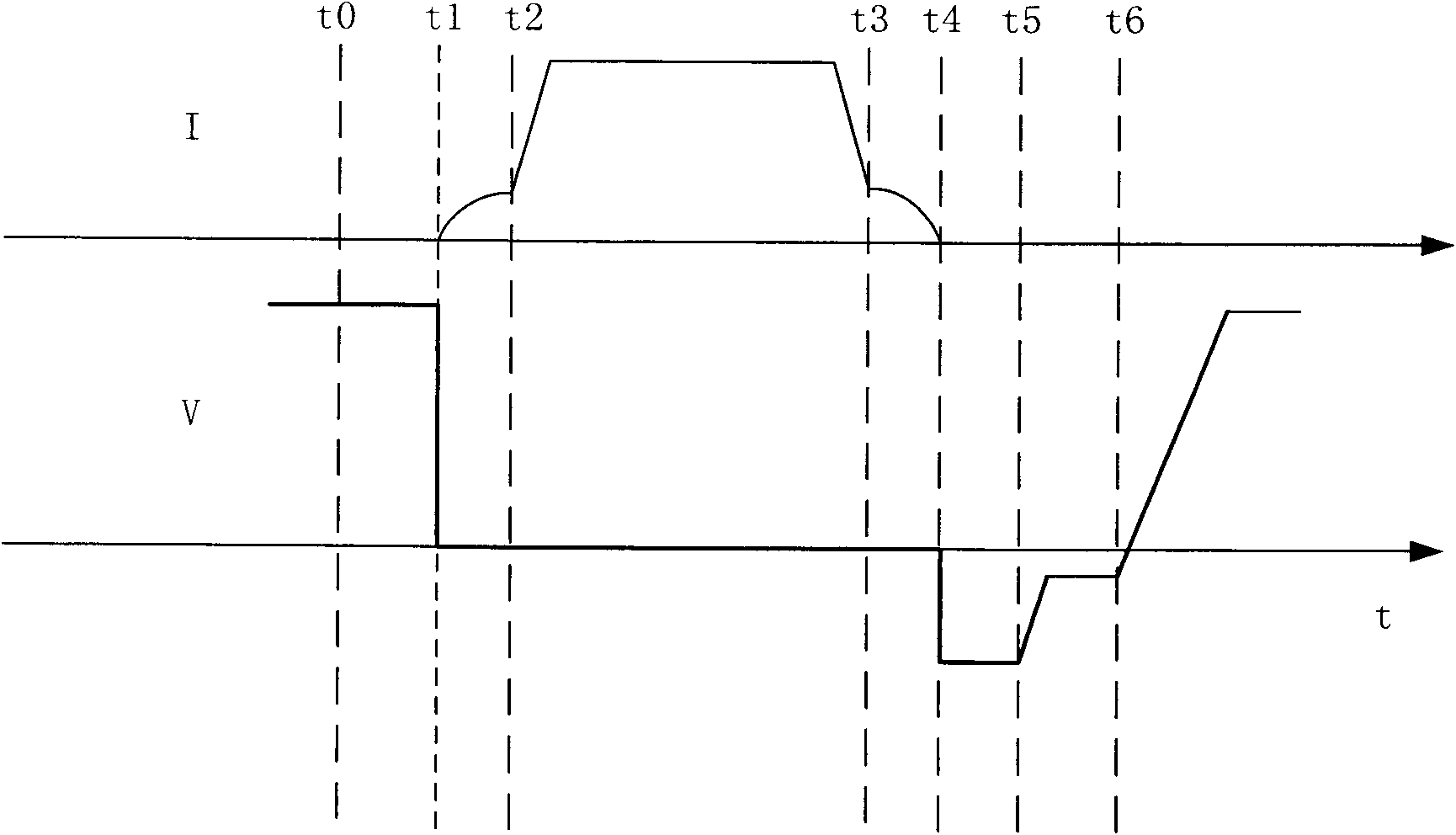
[0025] figure 2 It is the voltage and current cycle (20ms) waveform of the sample valve under the double injection mode of the synthetic test method.

[0026] At time t0, the sample valve Vt bears the positive high voltage generated by the high voltage source 1 circuit;

[0027] The test valve Vt and the auxiliary valve V2 are opened at time t1, and the resonant current in the high voltage source 1 flows through the test valve Vt;

[0028] Introduce the DC current in the DC large current source at time t2, and the test valve Vt bears the DC current during the conduction period;

[0029] At time t3, before the DC current goes out, the auxiliary valve V4 is opened, and the resonant current in the high voltage source 2 flows through the test valve Vt;

[0030] At time t4, the resonant curr...

Embodiment 2

[0034] In the synthesis test of the high-voltage direct current transmission converter valve, the basic working principle of the circuit of the present invention under the three-injection working mode:

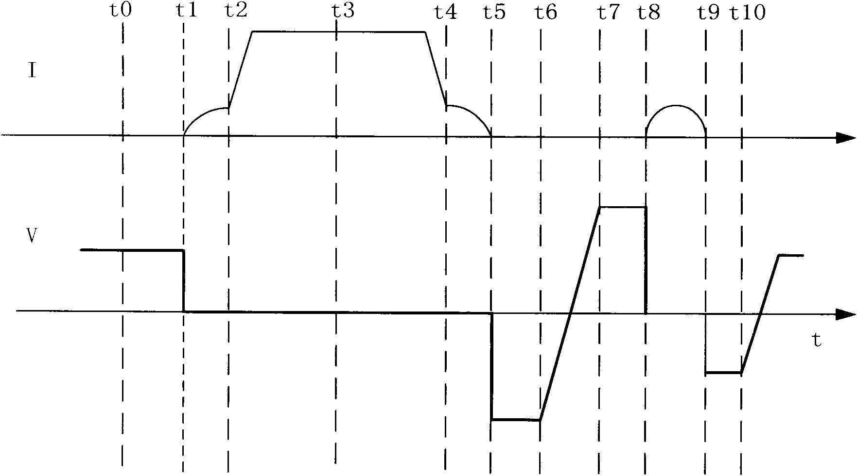
[0035] image 3 It is the voltage and current cycle (20ms) waveform of the sample valve under the synthetic test method three injection mode.

[0036] At time t0, the sample valve Vt bears the positive high voltage of the high voltage source 1;

[0037] The test valve Vt and the auxiliary valve V2 are opened at time t1, and the resonant current in the high voltage source 1 flows through the test valve Vt;

[0038] Introduce the DC current in the DC large current source 1 at time t2, and the test valve Vt bears the DC current during the conduction period;

[0039] Control the charging circuit T1, VS1, and C1 at time t3 to charge the high voltage source 1, so that its voltage returns to the voltage level at time t0;

[0040] At time t4, before the DC current goes out, the auxil...


PUM


Abstract

The invention relates to a composite test apparatus of a high-voltage direct current transmission converter valve. The composite test apparatus comprises a test valve Vt, a high voltage source (1), a high voltage source (2) and a direct current high current source. An auxiliary valve V5 in the direct current high current source is in series connected with the test valve Vt, so that a bridge arm of a 6 pulse bridge rectifier B6 in the direct current high current source is formed. The high voltage source (1), the high voltage source (2) and the test valve Vt are in parallel connection. The test valve Vt is in ground connection. And heavy currents of the direct current high current source are between 3000A to 5000A. According to the provided composite test apparatus in the invention, two independent high voltage sources are used for providing reverse high voltages and forward high voltages for a test valve during a blockout period, so that unsymmetrical blocking voltages are obtained; therefore, a voltage exerted on the test valve approaches one that is exerted on the test valve in an actual operation condition and thus test equivalence is good. Moreover, according to the apparatus, a control sequence is changed, so that several kinds of voltage combination can be realized; and thus, there are several selection choices on a test scheme with a flexible mode; and the application range of the apparatus is wide.

Description

technical field [0001] The invention relates to a test device for a direct current transmission converter valve, in particular to a synthesis test device for a high voltage direct current transmission converter valve. Background technique [0002] With the increase of the capacity of power semiconductor devices, the high-voltage direct current transmission technology based on high-voltage series semiconductor device technology has developed rapidly and has been widely used in the world, and has played a good role in long-distance power transmission and large-scale grid interconnection. Technical advantages have achieved good economic benefits. DC converter valve is the key equipment of DC transmission system. With the increase of DC transmission voltage and transmission capacity, the importance of reliable operation of DC converter valve becomes more and more prominent. In order to improve and guarantee the design quality of the DC converter valve, and ensure the safe and c...

Claims


Application Information

Patent Timeline
IPC IPC(8): G01R31/00G01R31/327
Inventor 汤广福查鲲鹏谢婷高冲
Owner CHINA ELECTRIC POWER RES INST
Why Eureka
Try Eureka