Supercharge Your Innovation With Domain-Expert AI Agents!

Rigid special-shaped micro-structural fiber rod used in dentistry

A micro-structured optical fiber and special-shaped technology, which is applied in dentistry, optical fiber bundles, medical science, etc., can solve the problems of large bending angle of the light-emitting part of the optical fiber bundle, low light transmission efficiency, and difficult assembly, etc., to achieve high light transmission efficiency , high light transmission rate, compact structure

Active Publication Date: 2013-12-25
NANJING CHUNHUI SCI & TECH IND
View PDF2 Cites 0 Cited by
  • Summary
  • Abstract
  • Description
  • Claims
  • Application Information

AI Technical Summary

Problems solved by technology

Although the application of the above two optical fiber bundles has achieved the main purpose of lighting, due to its own characteristics, there are still the following defects when used: ① Due to the complex optical fiber Working gas pipelines, atomizing gas pipelines, cooling water pipelines, and power lines, etc., the assembly of optical fiber bundles needs to face complex space cavities. Because the diameter of the optical fiber single filament is thin (diameter ≤ 50um), it is soft and easy to break, so the assembly is difficult.
②Because both ends of the optical fiber bundle are dipped in epoxy, there are microscopic gaps on the end surface. During treatment, blood will enter the optical fiber bundle due to capillary phenomenon. After long-term use, the hemoglobin in the blood will affect the lighting effect and distort the image , and the blood and water in the microholes on the end face of the fiber optic bundle can easily cause cross-infection
③ Due to fiber gaps and glue seams, the convergence rate of optical fibers is not high, and the optical transmission efficiency is not high
④The bending angle of the light-emitting part of the optical fiber bundle is large (≥110°), and the "neck extension" is short (≤1-2mm), making it difficult to manufacture and polish the optical fiber bundle

Method used


Image

  • Rigid special-shaped micro-structural fiber rod used in dentistry
  • Rigid special-shaped micro-structural fiber rod used in dentistry
  • Rigid special-shaped micro-structural fiber rod used in dentistry

Examples


Embodiment 1

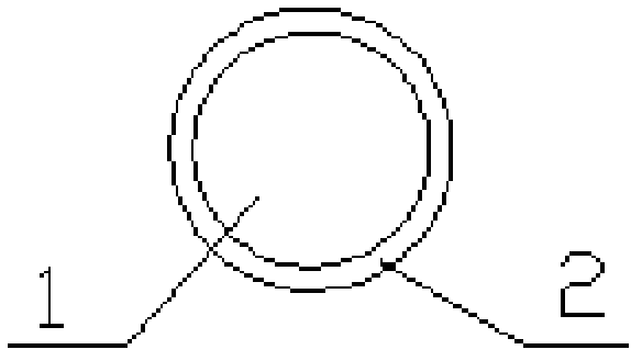
[0038] see figure 1 and figure 2 , the rod body of embodiment 1 is made by the glass mandrel 1 that diameter is 20mm outside the transparent glass leather tube 2, is drawn into rod through high temperature, and then is made through high temperature molding fusion, and the diameter of rod body 4 in round rod area is 2.5mm. The rod body 5 in the deformation zone has 4 bends, and from the left end of the deformation zone, the cross section of the rod body A in the first section of the deformation zone is crescent-shaped (see Figure 7 ), the section of rod B in the second deformation zone is still crescent-shaped (see Figure 7 ), the section of rod C in the third deformation zone is elliptical (see Figure 8 ), the cross-section of the rod D in the fourth section of the deformation zone changes from an ellipse to a circle. The cross-section of the rod body in the round rod area is circular (see figure 2 )

[0039] In the process of high-temperature drawing into rods, the...

Embodiment 2

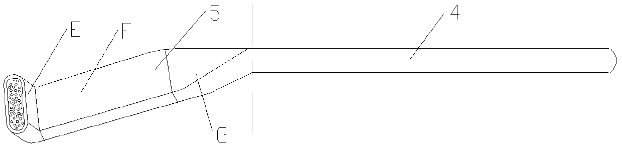
[0042] see image 3 and Figure 4 , the present embodiment uses about 1,700 glass optical fiber precursors with a diameter of 380-450um to pass through the transparent glass leather tube 2, then draws them into rods at high temperature, and then fuses them through high-temperature molding. 2.5mm diameter, fiber optic monofilament 3 rigid glass fiber rods with a diameter of 55um. The rod body 5 in the deformation zone has 2 bends. From the left end of the deformation zone, the cross section of the rod body E in the deformation zone is an elliptical rod body (see Figure 8 ), the section of rod F in the second deformation zone is rectangular (see Figure 9 ), the cross-section of the rod G in the third deformation zone is a transition from a rectangle to a circle. The cross-section of the rod body in the round rod area is circular (see Figure 4 ).

[0043] In the process of high-temperature drawing into rods, the temperature range of the rod-drawing furnace is controlled b...

Embodiment 3

[0046] see Figure 5 and Image 6 , is a rigid microstructure optical fiber rod with a diameter of 2.5mm formed by polymerizing organic glass 11 in the mold cavity. The rod body 5 in the deformation zone has 4 bends. Since the deformation begins, the cross-section of the rod body H in the first deformation zone For rectangular rods (see Figure 10 ), the cross sections of rods I in the second deformation zone and rods J in the third deformation zone are still rectangular (see Figure 10 ), the cross-section of the rod K in the fourth deformation zone is a transition from a rectangular shape to a circle 11. The cross-section of the rod body in the round rod area is circular (see Figure 4 ). The appearance of embodiment 3 is smooth and transparent, and the organic material is acrylate.


PUM


Abstract

The invention discloses a rigid special-shaped micro-structural fiber rod used in dentistry. A rod body comprises a round-rod-zone rod body and a deformation-zone rod body, and the deformation-zone rod body at least undergoes folding once. The cross section or transverse plane of the deformation-zone rod body can be crescent, oval, square or rectangular, orthogonal, circular, etc., and can be a complex of a plurality of special shapes. The fiber rod provided in the invention overcomes disadvantages of optical fiber bundles used in dental treatment at present and has the characteristics of adaptability to assembling of complex effective spaces, convenient operation, uneasy breaking, a compact and poreless transverse plane, high light transmission efficiency, etc.

Description

technical field [0001] The invention relates to a dental optical fiber lighting device, in particular to a dental rigid special-shaped microstructure optical fiber rod. Background technique [0002] Dental treatment lighting is usually long-distance (≥600cm), wide bright-field (16-18cm×6-8cm) halogen cold light lighting. Because the light source is outside the mouth and the light is not concentrated, when performing fine treatment on teeth, It is difficult to eliminate the shadows in the working area caused by the projection of the treatment equipment, which affects the treatment effect and quality. For this reason, in the 1990s, the American MDT company first developed the optical fiber dental treatment instrument, and applied the optical fiber lighting system to the dental treatment instrument, which can directly send the light to the inside of the oral cavity and to the working point of the working area, so that the operating field of vision It is clearer and brighter, r...

Claims


Application Information

Patent Timeline
Patent Type & Authority Patents(China)
IPC IPC(8): A61C19/06G02B6/04
Inventor 张振远朱云青赵锦琳潘维超黄晓云龚峰云
Owner NANJING CHUNHUI SCI & TECH IND
Features
  • R&D
  • Intellectual Property
  • Life Sciences
  • Materials
  • Tech Scout
  • Unparalleled Data Quality
  • Higher Quality Content
  • 60% Fewer Hallucinations
Learn More