Support device for rear axle assembly of automobile production line

A technology for automobile production lines and support devices, which is applied in metal processing, metal processing equipment, manufacturing tools, etc., can solve the problems of poor speed and balance of brakes and rear trailing arms, difficulty in meeting consistent production, and high labor intensity for operators. To achieve the effect of reducing the difficulty of assembly, wide range of use, and eliminating the dislocation of workpieces

Inactive Publication Date: 2012-06-13
力帆科技(集团)股份有限公司
View PDF9 Cites 3 Cited by
  • Summary
  • Abstract
  • Description
  • Claims
  • Application Information

AI Technical Summary

Problems solved by technology

[0003] 1) During assembly, workers need to hold the workpiece with their hands before connecting it to the body. Due to the heavy weight of the rear brake, rear trailing arm and other components, the labor intensity of the operator is extremely high, and it is easy to cause the workpiece to drop out. On the one hand, it will cause the workpiece On the other hand, it is possible to injure workers, and the safety is poor;
[0004] 2) When installing the spring and connecting the rear shock absorber, push the brake and the rear trailing arm upwards by manpower to compress the spring and then fix the shock absorber. Due to the large spring force, not only the labor intensity of the workers at this station is too high, but also And the speed and balance of pushing up the brake and rear trailing arm is poor, making the shock absorber connection difficult;
[0005] 3) The connection between the tie rod, the brake and the rear trailing arm is driven by manpower. Due to the large spring force and the small space at the connection, the assembly operation is extremely time-consuming and laborious.
[0006] 4) The assembly of the rear axle assembly requires two stations and 8 workers to complete, the assembly efficiency is low, and the assembly relies on the workers to position the components based on experience, the positioning accuracy and reliability are poor, and it is difficult to meet the consistency production requirements

Method used


Image

  • Support device for rear axle assembly of automobile production line
  • Support device for rear axle assembly of automobile production line
  • Support device for rear axle assembly of automobile production line

Examples


Embodiment Construction

[0027] Below in conjunction with accompanying drawing and embodiment, the present invention will be further described:

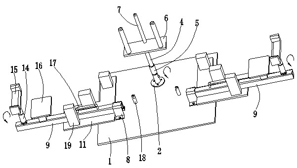
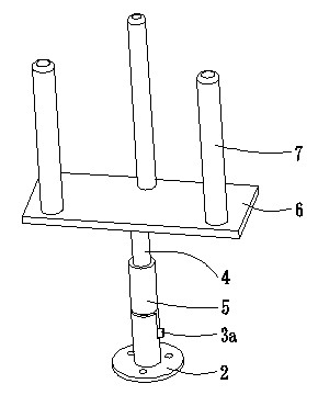
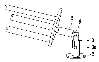
[0028] like figure 1 , figure 2 , image 3 As shown, the bottom plate 1 is a rectangular plate structure, and a base 2 is arranged in the center of the rear of the upper plate surface of the bottom plate 1. The base 2 is composed of a disc and a short tube. The disc is fixed to the bottom plate 1 by a plurality of bolts evenly distributed around the circumference Connection, a short tube perpendicular to it is fixed in the middle of the disc, and the short tube is sleeved with the lower end of the upright column 3 . The upper end of the short tube is provided with an opening from top to bottom, and the small post 3a in the middle of the upright post 3 is clamped into the opening to prevent the upright post 3 from rotating in the circumferential direction. The upper end of the upright column 3 is a flat cuboid, and the flat cuboid extends between the two ...


PUM


Abstract

The invention discloses a support device for a rear axle assembly of an automobile production line. An intermediate support mechanism and lateral support mechanisms are arranged on a bottom plate (1); the intermediate support mechanism comprises a base (2), an upright post (3), a first support post (4), a first sleeve (5), a first positioning plate (6), positioning rods (7) and the like; and each lateral support mechanism comprises a rectangular tube (9), a positioning pin (10), a second positioning plate (11), a support (12), a first support post (13), a second sleeve (14), a bearing seat (15), a lifting platform (16) and the like. The assembly of the automobile rear axle assembly can be facilitated, assembly difficulty is reduced, assembly quality and assembly efficiency are effectively improved, the number of the required operators is reduced, the labor intensity of workers is greatly reduced, the requirement of consistent production is met, and the support device has the characteristics of high safety and reliability, wide application range and the like, and is easy to operate.

Description

technical field [0001] The invention belongs to the technical field of automobile manufacturing, and in particular, particularly relates to a rear axle assembly support device on an automobile production line. Background technique [0002] The sport utility vehicle SUV has both the comfort of a sedan and the off-road performance of an off-road vehicle, and can carry both people and cargo, and has a wide range of applications. The rear axle assembly of SUV models is generally composed of rear brackets, rear brakes, transverse tie rods, rear trailing arms and other components, and springs and shock absorbers are connected between the rear axle assembly and the body. At present, when automobile manufacturers assemble the rear axle assembly on the production line, they install each component of the rear axle assembly on the body one by one. The shortcomings are: [0003] 1) During assembly, workers are required to hold the workpiece by hand and then connect it to the body. Due ...

Claims


Application Information

Patent Timeline
IPC IPC(8): B23P19/00
Inventor 张文旭
Owner 力帆科技(集团)股份有限公司
Why Eureka
Try Eureka