Gripping mechanism for replacing spatial on-orbit modules

A space, active mechanism technology, applied in the aerospace field, can solve the problems of low positioning accuracy, single function, complex structure, etc., and achieve the effects of precise position control, accurate capture and positioning, and small size

Inactive Publication Date: 2012-06-13
HARBIN INST OF TECH
View PDF5 Cites 32 Cited by
  • Summary
  • Abstract
  • Description
  • Claims
  • Application Information

AI Technical Summary

Problems solved by technology

[0004] The purpose of the present invention is to solve the existing problems of complex structure, single function, bulky volume, heavy mass, low positioning accuracy and inflexibility in the existing space-on-orbit module replacement gripping mechanism, and to provide a space-on-orbit module replacement gripping mechanism. Gripping mechanism for rail module replacement

Method used


Image

  • Gripping mechanism for replacing spatial on-orbit modules
  • Gripping mechanism for replacing spatial on-orbit modules
  • Gripping mechanism for replacing spatial on-orbit modules

Examples


specific Embodiment approach 1

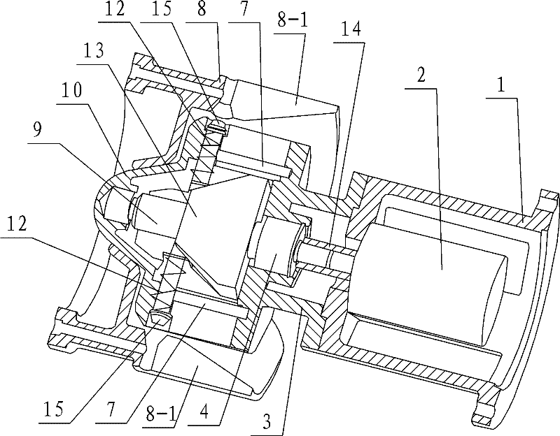
[0008] Specific implementation mode one: combine Figure 1 to Figure 8 Describe this embodiment, the grasping mechanism for space on-orbit module replacement in this embodiment includes an active mechanism and a passive frame 8, and the active mechanism includes an active frame 1, a stepping motor 2, a transition guide member 3, a positioning Pin 5, screw rod 9, tapered positioning body 10, wedge-shaped slider 13, coupling 14, two rows of bearings 4, two positioning columns 6, two delivery pipes 7, two springs 12, two pipe columns 15 and Two baffles 16; the transition guide member 3 includes a transition plate 3-1 and two guide bodies 3-2, and two guide bodies 3-2 are symmetrically arranged on the upper end surface of the transition plate 3-1; the stepper motor 2 Installed in the active frame body 1, the output end of the stepping motor 2 passes through the active frame body 1, the upper end surface of the active frame body 1 is fixedly connected to the transition plate 3-1 of...

specific Embodiment approach 2

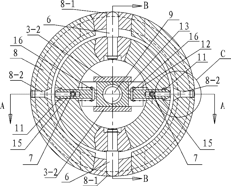
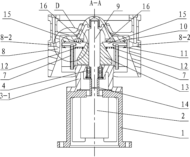
[0010] Specific implementation mode two: combination figure 2 , image 3 , Figure 5 and Figure 6 To illustrate this embodiment, the outer end of each pipe column 15 in this embodiment is conical, and the radial matching hole 8-2 is a tapered hole. Such setting is convenient for use together. Other components and connections are the same as those in the first embodiment.

specific Embodiment approach 3

[0011] Specific implementation mode three: combination figure 2 , image 3 , Figure 5 and Figure 6 To illustrate this embodiment, the grasping mechanism for space on-orbit module replacement in this embodiment further includes two sealing rings 11 , and one sealing ring 11 is sleeved on the outer end of each pipe string 15 . With such arrangement, the sealing between the pipe string and the radial matching hole is realized. Other compositions and connections are the same as those in the second embodiment.

[0012]Working process: During the connection process between the active connection mechanism and the passive frame body, the two positioning columns 6 radially arranged on the conical positioning body 10 cooperate with the first gap 8-1 on the passive frame body 8, and at the same time the passive frame body 8 The conical hole in the center cooperates with the top of the conical positioning body 10, and both play a positioning role together. Now, start the stepper m...


PUM


Abstract

A gripping mechanism for replacing spatial on-orbit modules relates to a gripping mechanism for replacing spatial modules, and aims to solve problems that an existing gripping mechanism for replacing spatial on-orbit modules is complex in structure, single in function, large in volume, heavy in weight and low in positioning precision and is inflexible. A stepping motor is mounted in a driving rack, a transition plate is connected onto an upper end surface of the driving rack, a conical positioning piece is disposed on the upper end surface of the transition plate, a driven rack is covered on the outer portion of the conical positioning piece, two positioning columns arranged radially are symmetrically mounted on the lower portion of the conical positioning piece, the upper end of a screw is connected with the conical positioning piece in a threaded manner, a wedge-shaped slider is connected onto the screw, the lower end of the screw is connected with the stepping motor, second notches are arranged on the conical positioning piece, tubular columns are mounted on the tops of the second notches in a clamped manner, conveying pipes are communicated with counter bored holes of the tubular columns, inclined surfaces of the tubular columns are abutted to the wedge-shaped sliders, and a spring is arranged between each of catches and the conical positioning piece. The gripping mechanism is used for on-orbit module service for a spacecraft and on-orbit connecting tasks.

Description

technical field [0001] The invention relates to a grasping mechanism for replacing a space module, in particular to a grasping mechanism for replacing a space on-orbit module, and belongs to the technical field of aerospace. Background technique [0002] With the rapid development of the world's aerospace industry in the 21st century and the continuous deepening of space exploration, space on-orbit technologies such as satellite capture and recovery, on-orbit assembly and maintenance, and scientific experiment load care have gradually attracted the attention of various countries, thus making on-orbit capture (OOC, On-Orbit Capture) technology has become a key technology that must be solved in On-Orbit Servicing (OOS, On-Orbit Servicing). [0003] On-orbit capture technology refers to the technology to capture space targets without human or unmanned participation. As early as the 1970s and 1980s, with the continuous expansion of space missions, in 1984, the United States use...

Claims


Application Information

Patent Timeline
Patent Type & Authority Applications(China)
IPC IPC(8): B25J15/00B64G4/00
Inventor 田浩赵阳王有懿游斌弟马超
Owner HARBIN INST OF TECH
Why Eureka
Try Eureka