
Novel anti-icing and deicing device for airfoils of airplane

A new type of airfoil technology, applied in the field of anti-icing, anti-icing and de-icing device, and de-icing device for the leading edge of aircraft airfoil (wing/tail), which can solve the problem of high energy consumption, long de-icing time, and reduced lift. Small and other problems, to achieve the effect of simple equipment, compact structure and energy reduction

Inactive Publication Date: 2012-06-13
SOUTHEAST UNIV
View PDF5 Cites 21 Cited by
  • Summary
  • Abstract
  • Description
  • Claims
  • Application Information

AI Technical Summary

Problems solved by technology

Icing not only increases the weight of the aircraft and reduces the efficiency of the propellers, which in turn reduces the thrust available to the engines, but also interferes with airflow, causing increased drag and reduced lift
The icing on the wing, empennage and control surface will destroy the flow pattern on the wing surface, leading to the increase of the stall speed, thus causing flight accidents
[0003] In order to reduce the impact of icing on the flight of the aircraft and increase the safety margin of the aircraft, the hot gas anti-icing technology is widely used for the anti-icing of the wings and tail of the aircraft. Although this anti-icing technology can prevent and deicing to a certain extent, it takes a long time to deicing and consumes a lot of energy. At the same time, due to its large thermal inertia, it is easy to form ice lumps behind the heating zone.

Method used


Image

  • Novel anti-icing and deicing device for airfoils of airplane
  • Novel anti-icing and deicing device for airfoils of airplane
  • Novel anti-icing and deicing device for airfoils of airplane

Examples


Embodiment Construction

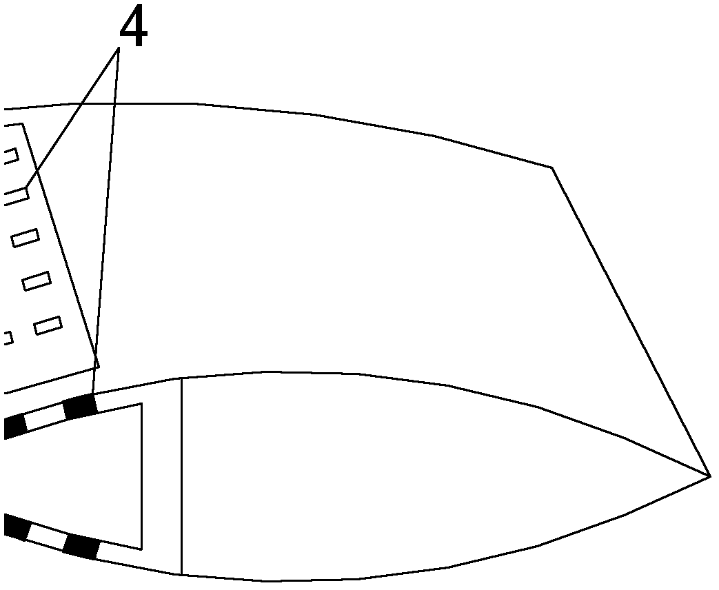
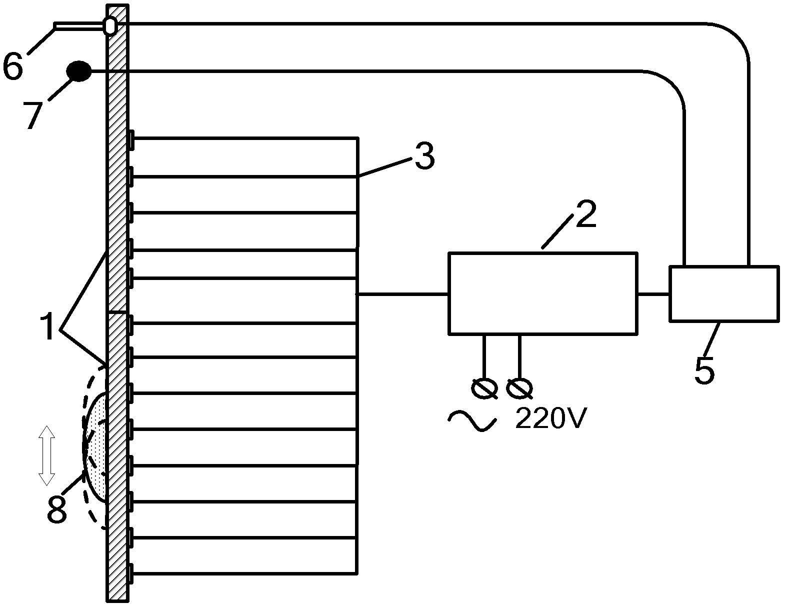
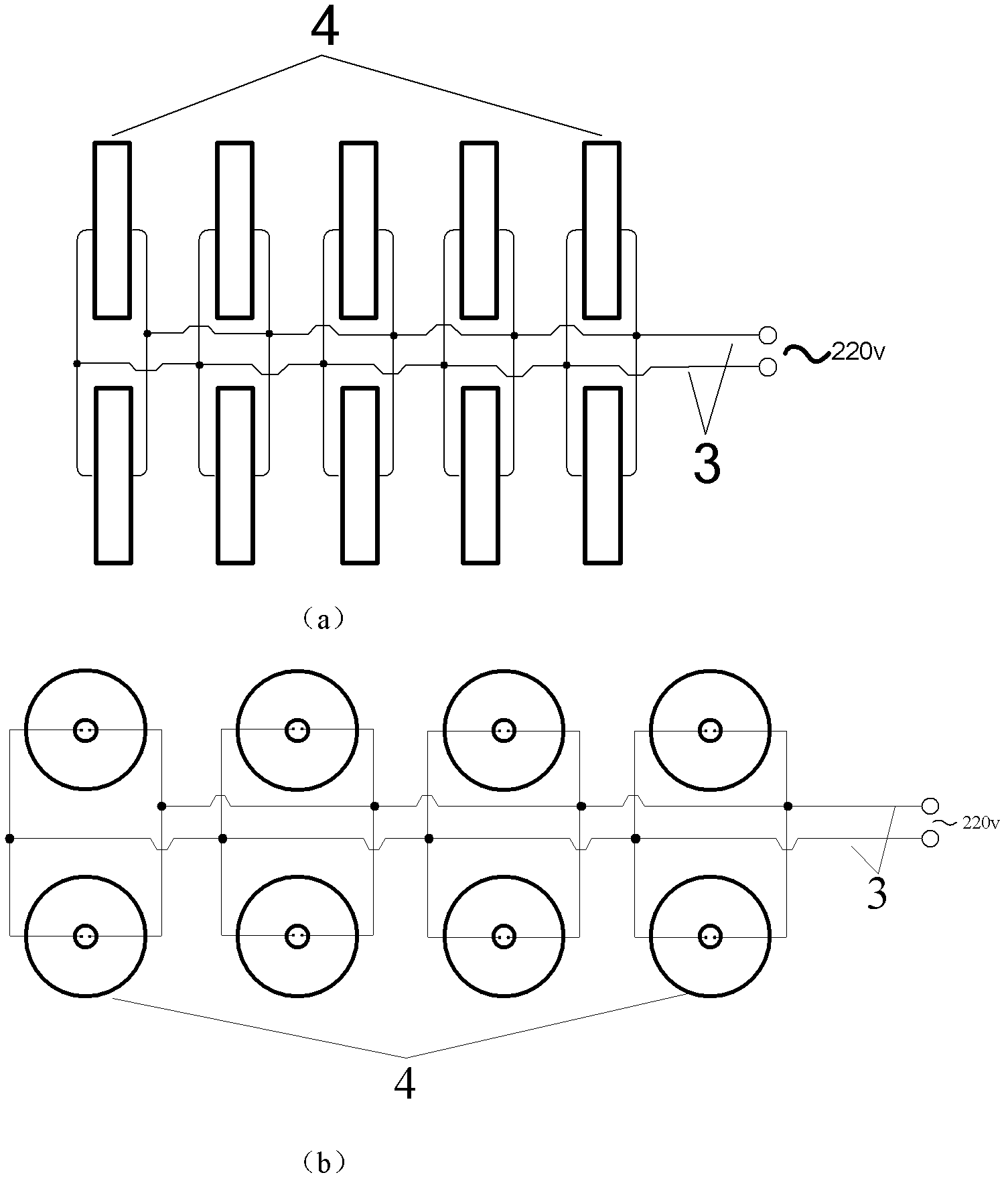
[0018] The accompanying drawings disclose, without limitation, the structural schematic diagrams of the preferred embodiments involved in the present invention; the technical solution of the present invention will be described in detail below in conjunction with the accompanying drawings.

[0019] Such as Figures 1 to 3 As shown, the novel anti-icing and de-icing device for aircraft airfoil according to the present invention includes a skin corresponding to the leading edge of the wing, a program controller, an atmospheric temperature sensor for detecting the temperature of the external atmospheric environment, and a The icing intensity signal device for detecting the thickness of the ice layer on the outer surface of the skin, the atmospheric temperature sensor and the icing intensity signal device are all installed on the outer surface of the skin; the inner surface of the skin is fixedly installed with an ultrasonic deicing unit module, this The invention is fastened to th...


PUM


Abstract

The invention discloses a novel anti-icing and deicing device for airfoils of an airplane. The device comprises skin, a program controller, an atmospheric temperature sensor and an icing strength annunciator, wherein ultrasonic deicing unit modules are fixedly arranged on the inner surface of the skin, and each ultrasonic deicing unit module comprises a plurality of piezoelectric ceramic transducers; each piezoelectric ceramic transducer is connected with an ultrasonic generator by a connecting cable; the ultrasonic generator is connected with a power supply; and the program controller controls the ultrasonic generator to start and stop according to temperature signals fed back by the atmospheric temperature sensor and controls the power of the ultrasonic generator and the number of the operating ultrasonic deicing unit modules according to ice layer thickness signals fed back by the icing strength annunciator. Therefore, by using the novel anti-icing and deicing device for the airfoils of the airplane, ice layers on the surfaces of the airfoils and the leading edge of an empennage can be effectively removed in real time during the flight of the airplane; the device is efficient, energy-saving, safe and reliable; ice can be thoroughly removed; and the flight safety of the airplane is ensured.

Description

technical field [0001] The invention relates to an anti-icing and de-icing device, in particular to an anti-icing and de-icing device for the leading edge of an aircraft airfoil (wing / tail), and belongs to the field of aircraft de-icing and anti-icing. Background technique [0002] Aircraft icing caused by icy and snowy weather is one of the main causes of aircraft flight accidents. According to statistics, about 9% of aircraft accidents are caused by icing. When the aircraft flies in icy conditions, the flight quality and flight performance will be greatly affected. Icing not only increases the weight of the aircraft and reduces the efficiency of the propellers, which in turn reduces the thrust available to the engines, but also interferes with airflow, causing increased drag and reduced lift. The icing on the wing, empennage and control surface will destroy the flow pattern on the wing surface, cause the stall speed to increase, and cause flight accidents. [0003] In or...

Claims


Application Information

Patent Timeline
Patent Type & Authority Applications(China)
IPC IPC(8): B64D15/18B64D15/22
Inventor 陈振乾李栋查翔
Owner SOUTHEAST UNIV
Learn More