Steel for lower plate of cargo oil tank of tanker

A technology of cargo oil tank and bottom plate, applied in the field of ship plate steel, can solve the problems of bulky cargo oil tank, long construction time and high maintenance cost, and achieve the effect of reducing maintenance cost, inhibiting local corrosion and prolonging service life

Inactive Publication Date: 2012-06-13
CENT IRON & STEEL RES INST
View PDF5 Cites 17 Cited by
  • Summary
  • Abstract
  • Description
  • Claims
  • Application Information

AI Technical Summary

Problems solved by technology

[0004] At present, the method of primer coating or metal spraying is mainly used to reduce the corrosion of the bottom plate. However, due to the large volume of the cargo oil tank, the method of painting and spraying will inevitably bring about long construction time and high maintenance costs. During the construction of the protective layer, microscopic defects on the surface will also be brought about. These microscopic defects

Method used


Image

  • Steel for lower plate of cargo oil tank of tanker
  • Steel for lower plate of cargo oil tank of tanker
  • Steel for lower plate of cargo oil tank of tanker

Examples


Embodiment 1

[0035] Embodiment 1 (simulated cargo oil tank pitting method)

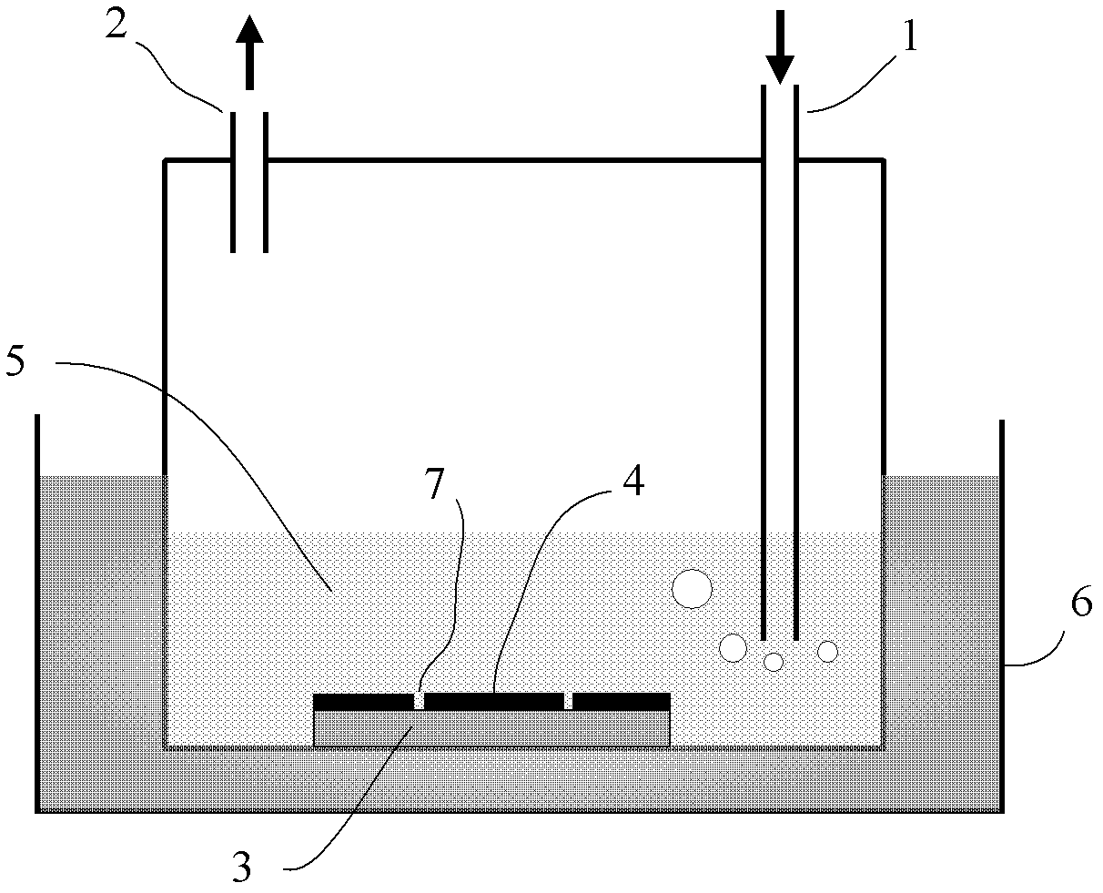
[0036] figure 1 In order to simulate the pitting corrosion of the bottom plate of the cargo oil tank. For each of the above-mentioned 40mm (length) × 40mm (width) × 15mm (thickness) square samples of 3 pieces, the test surface is polished to 600#, and cleaned with alcohol and acetone. Carry out a test on a 40mm×40mm surface of the sample, first coat the non-test surface with epoxy resin, and only coat the oil sludge at the bottom of the cargo oil tank of the actual oil tanker evenly on the test surface, and leave 4 small holes of φ2mm bare (see figure 1 7 positions) to simulate the starting point of localized corrosion.

[0037] During the test, the sample is figure 1 The method in is placed at the bottom of the reaction vessel, a certain amount of 10% NaCl aqueous solution is injected into the vessel 5, and the water temperature in the constant temperature water bath 6 is set to 40°C, and the following two ga...

Embodiment 2

[0038] Embodiment 2 (laboratory hanging piece)

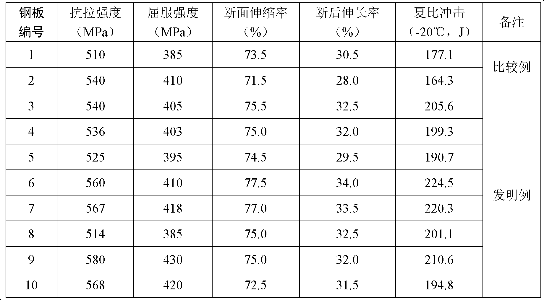
[0039] This test is an accelerated corrosion coupon test in the laboratory to simulate the steel surface in high concentration Cl - , The expansion rate of localized corrosion in high acidity environment. For each of the above-mentioned 50mm (length) × 25mm (width) × 5mm (thickness) square samples of each of the 5 pieces, each surface of the sample is polished to 600#, after cleaning with alcohol and acetone, measure the size of the sample and weight, test the two 50mm×25mm faces of the sample, and seal the other non-test faces with epoxy resin. The test solution is 10% NaCl aqueous solution, the pH value is adjusted to 0.6 with HCl, the test temperature is 40° C., and the soaking time is 72 hours. After the test, the corrosion products were removed, the corrosion weight loss was measured, and the corrosion rate was evaluated. The test results are shown in Table 3.

[0040]

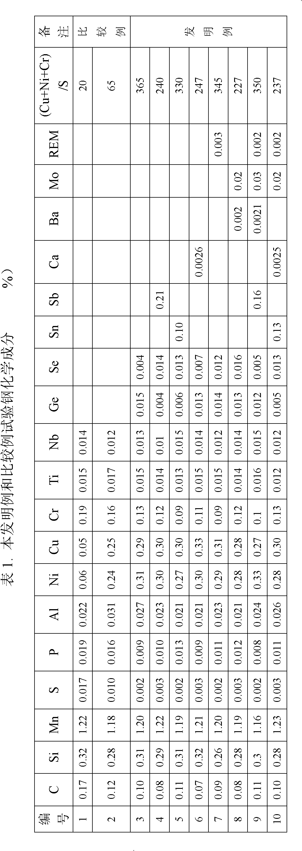
[0041] Table 2. Examples of the present invent...


PUM


Abstract

The invention provides steel for the lower plate of a cargo oil tankof a tanker, which belongs to the technical field of ship plate steel. The steel comprises, by mass, 0.01 to 0.3% of C, 0.02 to 2% of Si, 0.1 to 2.0% of Mn, no more than 0.01% of S, no more than 0. 02% of P, 0.05 to 2.0% of Ni, 0.05 to 2.0% of Cu, 0.005 to 1.0% of Cr, 0.0005 to 0.3% of Se, 0.0005 to 0.3% of Ge, with the balance being Fe; preferably, (Cu + Ni + Cr)/S is 200 to 480. The steel can also comprise one or more selected from the group consisting of 0.0005 to 0.3% of Sn, 0.0005 to 0.3% of Sb and 0.0005 to 0.3% of Te, and/or one or more selected from the group consisting of 0. 0005 to 0.3% of W, 0.0005 to 0.3% of Mo, 0.0005 to 0.3% of Co and 0.0005 to 0.3% of REM, and/or one or more selected from the group consisting of 0.0001 to 0.2% of Ca, 0.0001 to 0.2% of Mg, 0.0001 to 0.2% of Sr and 0.0001 to 0.2% of Ba. The steel has the advantages of excellent local corrosion resistance under the conditions of a high concentration of Cl<-> and a high acidity and effective prolongation of the service life of a steel plate when the steel plate is coated by a protective layer or is exposed.

Description

technical field [0001] The invention belongs to the technical field of ship plate steel, and in particular relates to a steel for the lower floor of an oil tanker's cargo oil tank. The steel for the lower floor of an oil tanker's cargo oil tank used in a coated protective layer or in a bare state can significantly improve - , Resistance to pitting localized corrosion in high acidity environments. Background technique [0002] In recent years, incidents of oil pollution to the marine environment caused by shipping have occurred frequently, and the corrosion of oil tankers, especially the corrosion of cargo oil tanks, has attracted increasing attention. The cargo oil tank is the main structure for carrying crude oil, and the protection of its bottom plate is the key to preventing crude oil leakage. Some studies in recent years have found that in the cargo oil tanks of actual large oil tankers, severe pitting corrosion occurs on the lower bottom plate, most of which are 10-30m...

Claims


Application Information

Patent Timeline
IPC IPC(8): C22C38/58C22C38/60C22C38/42
Inventor 苏航柴锋杨才福罗小兵李丽薛东妹潘涛王瑞珍沈俊昶王卓梁丰瑞
Owner CENT IRON & STEEL RES INST
Why Eureka
Try Eureka