Eureka AIR delivers breakthrough ideas for toughest innovation challenges, trusted by R&D personnel around the world.

Slewing system for hybrid hydraulic excavator and driving and braking method for slewing system

A technology of hybrid power and slewing system, applied in the direction of earth mover/shovel, construction, etc., can solve the problem of low energy recovery efficiency, and achieve the effect of improving efficiency, improving reliability and easy realization.

Active Publication Date: 2012-06-13
HARBIN INST OF TECH
View PDF5 Cites 20 Cited by
  • Summary
  • Abstract
  • Description
  • Claims
  • Application Information

AI Technical Summary

Problems solved by technology

[0004] The present invention aims to solve the problem of low energy recovery efficiency when braking the slewing system of the existing hydraulic hybrid excavator, and provides a slewing system of the hydraulic hybrid excavator and a driving and braking method for the slewing system

Method used


Image

  • Slewing system for hybrid hydraulic excavator and driving and braking method for slewing system
  • Slewing system for hybrid hydraulic excavator and driving and braking method for slewing system

Examples


specific Embodiment approach 1

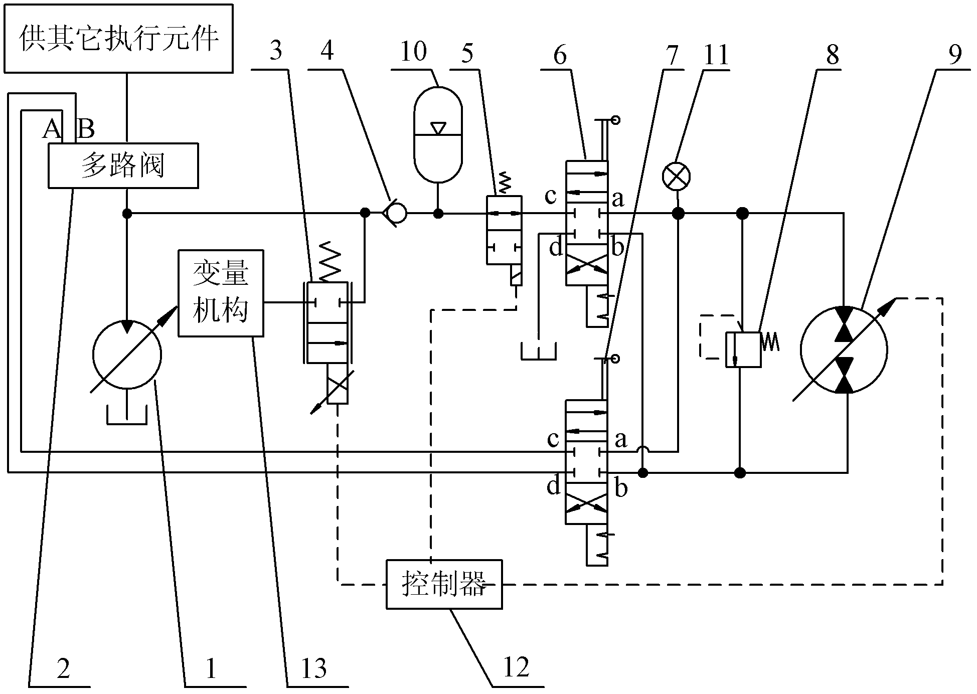
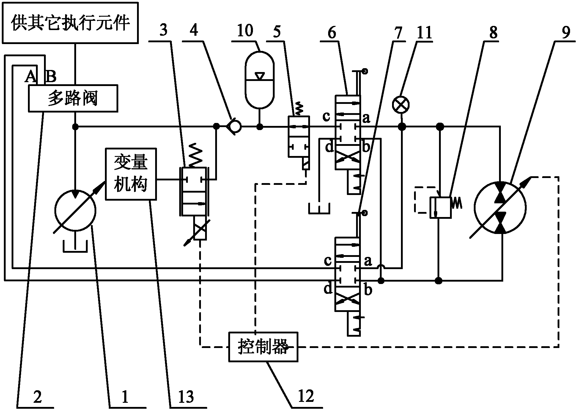
[0019] Specific implementation mode one: the following combination figure 1 Describe this embodiment. The hydraulic hybrid excavator slewing system described in this embodiment includes a variable pump 1 and a multi-way valve 2. It also includes an electric proportional throttle valve 3, a one-way valve 4, an electronically controlled on-off valve 5, The first manual reversing valve 6, the second manual reversing valve 7, the relief valve 8, the hydraulic pump / motor 9, the hydraulic accumulator 10, the pressure sensor 11 and the controller 12,

[0020] The oil inlet port of the multi-way valve 2 is connected with the high-pressure oil port of the variable pump 1, the A port of the multi-way valve 2 is connected with the d port of the second manual reversing valve 7, and the B port of the multi-way valve 2 is connected with the second manual reversing valve Port c of 7, port b of the second manual reversing valve 7 is connected to the low-pressure oil port of the hydraulic pump...

specific Embodiment approach 2

[0024] Specific implementation mode two: the following combination figure 1 Describe this embodiment. This embodiment is based on the driving and braking method of the hydraulic hybrid excavator swing system described in Embodiment 1. The swing system in this embodiment replaces the motor in the existing swing system with a hydraulic pump / motor. 9. After installing other related components, switch the working mode through the switching of two manual reversing valves.

[0025] The slewing system described in the present invention has two working modes in actual work:

[0026] The first type: hybrid power mode, which adopts the slewing system described in the present invention to realize driving and braking. The first manual reversing valve 6 is adjusted to the upper position and the second manual reversing valve 7 is adjusted to the neutral position. The slewing system is put into a hybrid power mode with the function of recovering energy. This mode utilizes the feature that t...


PUM


Abstract

The invention discloses a slewing system for a hybrid hydraulic excavator and a driving and braking method for the slewing system, and belongs to the technical field of hydraulic systems of excavators. The invention solves the problem that the energy recovery efficiency is low when the conventional slewing system of the hybrid hydraulic excavator is braked. The slewing system comprises a variabledisplacement pump, a multiway valve, an electro-hydraulic proportional throttle valve, a one-way valve, an electric control switch valve, a first hand-operated direction valve, a second hand-operateddirection valve, an overflow valve, a hydraulic pump / motor, a hydraulic accumulator, a pressure sensor and a controller. Based on the driving and braking method for the slewing system, the first hand-operated direction valve is adjusted to an upper position and the second hand-operated direction valve is adjusted to a middle position, so that the slewing system enters a hybrid mode with an energyrecovery function, and the slewing system is driven and braked in the mode by utilizing the characteristic that the hydraulic pump / motor can work in four quadrants. The slewing system is suitable forthe hybrid hydraulic excavator.

Description

technical field [0001] The invention relates to a rotary system of a hydraulic hybrid excavator and a driving and braking method of the rotary system, belonging to the technical field of excavator hydraulic systems. Background technique [0002] Excavator is a kind of engineering machinery with a very wide range of applications. The current excavators generally have the disadvantages of high fuel consumption and poor emission. The main reason is that the efficiency of its hydraulic system is low. With the continuous aggravation of the energy crisis and the continuous improvement of environmental protection requirements, the energy-saving research on the excavator hydraulic system has gradually become a research hotspot. [0003] In recent years, relevant scholars have developed a number of energy-saving technologies to improve the efficiency of the excavator hydraulic system, but these technologies cannot eliminate the throttling loss of the main valve port of the hydraulic ...

Claims


Application Information

Patent Timeline
IPC IPC(8): E02F9/08E02F9/22
Inventor 姜继海沈伟罗念宁于安才张健赵川
Owner HARBIN INST OF TECH
Why Eureka
Eureka Blog
Learn More